background image

15

STEP T

W

O

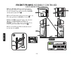
2.14 

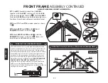
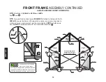
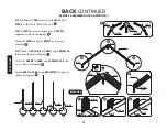
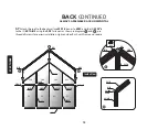
Attach the (2) L08A-X to 601A’s and 604’s

See         and        .

2.15 

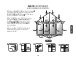
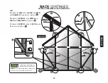
To square front section loosen S04/ML01 attached to the tops of the (2) 

L08A-X’s, square the frame with carpenter square or use a measuring tape to 

make sure corner measurements are the same, tighten L08X’s to hold square-

ness, L08A-X should be attached 1” up from bottom bolt see       .

601B

L08D

L08A-X

601B

Y3-2

603C

L08D

L08A-X

604-R

601A-FR

601A-FL

Y3-1

Y1

Y1

604-L

619

W02

W02

W02T

W02T

Y2-2

Y2-1

603A

GRANDIO

T I P

Set front  aside in a shaded 
area, do not lay on grass, 

prolonged sunlight through the polycarbon-
ate panels will burn if placed directly on top 
of plants during the intense sun of the day.

Use measuring tape to 

measure from corner to 

corner to assure square. 

L08A-X

601A-FR

S04/ML01

606-WS

606-WS

ML01 

S04

L08A-X

619

604-R

FRONT FRAME ASSEMBLY CONTINUED

ALWAYS ASSEMBLE FRONT HORIZONTAL

Summary of Contents for Ascent 8x8 KIT

Page 1: ...U S E S GRANDIO GREENHOUSEUSERMANUAL 2013 Grandio Greenhouses Backyard Living Source Inc All rights reserved 2015 Manual Edition Extendable Greenhouses Grandio Ascent 8x8 Shown In Image 2015 GRANDIO A...

Page 2: ...sure your Grandio Greenhouse will be covered on your policy Call your local utilities companies before digging Do not attempt to begin construction on a windy day Your greenhouse should be built on a...

Page 3: ...de The clear side has a UV coating and we recommend marking a small x on a corner of each panel to determine which side has the UV Coating as you cannot visually determine with your eye in the case of...

Page 4: ...e toward the sun The side covered in white film will always face the interior of the greenhouse We suggest you peel all film off completely prior to assem bly and use a permanent marker to place a sma...

Page 5: ...SIDE 603B 616 602A 602A L08C X 602B L08C 602B 610 602A L08C X 602B L08C 615 6 603B 603B 602C L08B X 602D L08A X 610 610 618 618 Y5 Y4 2 Y2 1 Y2 2 Y1 Y1 Y2 1 Y1 Y3 1 Y3 2 Y9 Y9 Y6 Y7 Outside View 606...

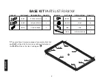
Page 6: ...LY STEP SIX INTERIOR ROOF SUPPORTS Introduction 1 Safety Instructions 2 Prepare For Assembly 3 Diagram of Assembled Grandio Elite 8x8 4 Base Kit Assembly Information 6 Base Kit Parts Lists 7 Base Kit...

Page 7: ...ind Conditions If you live in a windy location there is no way to build a 100 storm safe greenhouse but there are a number of things you can do to minimize the chance of damage Ensure that the base is...

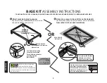
Page 8: ...4 BA S1 BA S2 BA S1 BA S2 BA C3 BA C3 BA C3 BA C3 1 1 Layout all base kit pieces to prepare for assembly Note that one BA S1 will be at the front and one will be at the back and the BA S2 s will be o...

Page 9: ...Note Placement of BA S1 will be at front and the back while the BA S2 s will be the sides of your greenhouse base 1 3 For ground installation only insert the 4 BA A1 s and 4 BA S03 ML01 combos to the...

Page 10: ...ST BE LEVEL SQUARE FOUNDATION MUST BE PROPERLY ANCHORED PRIOR TO GREENHOUSE ASSEMBLY B Holes are present in base kit for anchoring bolts You determine and aquire proper fastener prior to installation...

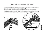
Page 11: ...front frame of your greenhouse If possible try to find a shady area protected from the wind Panels can burn grass and plants if in direct light GRANDIO T I P We recommend watching our how to assembly...

Page 12: ...n The UV Protected side is covered with transparent film and must face toward the sun The side covered in white film will always face the interior of the greenhouse We suggest you peel all film off co...

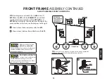
Page 13: ...he 619 with the S04 ML01 nut and bolt combos Note the orientation of the 601A FR and 601A FL and the holes that should be at the top of the piece and face to the front see the diagram to the right sho...

Page 14: ...bonate panels in place If it seems too tight slide fingers or nut driver along edges gently stretching the 606 WS to allow room for panels to fit 2 9 Insert Y1 polycarbonate panels into place make su...

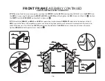
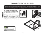
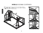
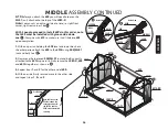
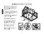
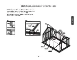
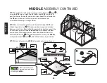
Page 15: ...n the S05 screws as shown in Tighten the W02T s with the S04 ML01 nut and bolt as shown in 2 13 Attach the L08A X s to 601A s and 604 s to square front section loosen S04 ML01 attached to the bottom o...

Page 16: ...ttom bolt see 601B L08D L08A X 601B Y3 2 603C L08D L08A X 604 R 601A FR 601A FL Y3 1 Y1 Y1 604 L 619 W02 W02 W02T W02T Y2 2 Y2 1 603A GRANDIO T I P Set front aside in a shaded area do not lay on grass...

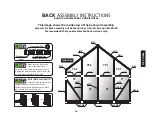
Page 17: ...ure the UV coated side of the panel faces outward as indicated on the panels Avoid placing the polycarbonate panels in the sun or near plants until fully assembled GRANDIO T I P Transparent Film Outsi...

Page 18: ...to L08A using S04 ML01 fastener as shown in diagram Attach 2 603B s to L08A using S04 ML01 fasten ers as shown in diagram Attach 602C to L08A using S04 ML01 fastener as shown in diagram 603B 602C 601...

Page 19: ...in place Attach L08B to 2 601A B s 602D s and the 602C with S04 ML01 fasteners as shown in diagram and Pre thread all fasteners into assigned channels and align with L08B for ease of installation 3 6...

Page 20: ...ers as shown in diagram and pre thread all screws for easiest installation tighten when flush with frame and square 602C 601A B 601A B Y4 1 Y4 2 Y1 Y1 Y1 Y1 W01 601B 601B S05 603A W01 W02 W02 603B 603...

Page 21: ...D s and L08A with S04 ML01 as shown in C Attach 2 L08B X s to the 2 601A s with fasteners as shown in L08B X L08B X GRANDIO T I P Square by loosening bolts attached to the tops of the L08B X use measu...

Page 22: ...ge the base kit front framing etc Damage caused by improper installation is not warrantable ML01 NUT S04 BOLT W05 CLIP BA S2 601A ML01 S04 Inside View Front Right side BA S1F BA S2 BA S1 4 1 We recomm...

Page 23: ...in and with the nut and bolt combos 4 4 Attach the front section 619 to the base using S04 ML01 fasteners as shown in then attach the threshold support to the inside of the 619 with 4 self tapping sc...

Page 24: ...W05 clips will catch the under edge of the front base kit and then slide upward attach ing to the bottom of the 601A s and the 604 s you will switch out the hardware that was originally used to the W...

Page 25: ...4 8 Use the 5 remaining W05 clips to attach the backwall where the 601A s meet the corner of the base as shown in and where 602D s and the 602C meet the BA S1B see Then use W05 Clip combos to attach t...

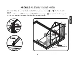
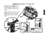
Page 26: ...01B Inside View S04 ML01 25 STEP FOUR MIDDLE ASSEMBLY CONTINUED 4 8 With 2 people attach the ridge to front and back by sliding into place as shown in and using S04 ML01 fasteners attach the 607 to th...

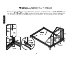
Page 27: ...601B using S04 ML01 nut and bolt See 2 Now move the loosened S04 ML01 nut and bolt currently attached to the 601A upward to firmly secure the L08C X 609 and 601A together as shown in 3 Repeat steps 1...

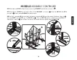
Page 28: ...the L08C X Be sure the 602A is aligned and sitting flush on top of the base kit See for reference 2 Hold the 602A in place and attach the top of the 602A to the 609 using S04 ML01 nut and bolt As sho...

Page 29: ...oof section Note the exact placement on the outside see Do not attach remaining 602B s to lower roof section until roof vents are attached 609 602A ML01 S04 602B Inside View 602B 609 607 EXACT PLACEME...

Page 30: ...your discretion however must be in the middle for support do not place nearest the front or back as you will need a 602B support to keep in window vent in place Place directly across from each other...

Page 31: ...f Y7 s will align when greenhouse is level S04 ML01 L08C X 609 Loosen 4 15 Install plastic strip 606 WS before inserting polycarbonate sheet Y6 s see You will attach the Y6 CAP s to the top of each Y6...

Page 32: ...dle to the second and third pins of HQC02 Then attach HQC02 into 603C s track with S04 ML01 nuts and bolts see 603B 618 616 616 603C 616 Z04 HQC02 Y8 Y8 HQC01 Handle Inside view of 603C 603B 602B W04...

Page 33: ...e gutters are in place You may want to place a piece of tape on the panel to prevent sliding as shown in the diagram once the panels are in place 4 21 Slide 610 Gutters into 609 s groove as shown in t...

Page 34: ...utters on both front and back as shown below Squeeze a small amount of rubberized silicone or construction adhesive into the ends of ridge to secure pressure fit end caps It is recommended to caulk an...

Page 35: ...8A 622 R UP UP Side View 622 J08A Bottom View Inside View J04 OPTIONAL This image shows the inside view of Right Door Assembly All parts for door assembly will be found in box GRA ELI 8A and GRA ELI 8...

Page 36: ...r and these need to be aligned with the lock mechanisms This will save you from assembling the wrong way 5 1 Insert J08A into the bottom of the 622 note the bottom groove is smaller than the top groov...

Page 37: ...he same instructions for the other door making sure that the 622 L and 622 R with the double ball catch match up so doors will latch closed and slide properly Y6 Y6 623B 623A 620 622 R Double Ball Cat...

Page 38: ...he greenhouse line up hanging door track L21 with door header 603D move bolts on L21 to line up with bolt holes on door header 603A From the inside hand tighten the ML01 nut while the person outside i...

Page 39: ...y latch in the middle 5 9 Attach the door handles 622 HNDL to both doors using the 622 HNDL NUT BOLT provided to both doors as shown below in and DOOR INSTALLATION Outside View Inside View Top Bottom...

Page 40: ...L28 to L21 with S04 ML01 and L28 to 601A with S02 ML01 as shown below in diagram and Check that the L21 and L28 s are square Attach 2 J07 to the ends of L21 see The L28 should align square to the 601A...

Page 41: ...m 6 2 Use S04 ML01 to attach the L08C s to 601B s and 602B s on the inside of roof midway between the roof and the gutters for additional roof support See diagram 6 3 You may remove all stickers now w...

Page 42: ...7 mm 47 5 16 in 1201 mm 21 7 8 in 555 mm 17 in 431 mm 68 7 8 in 1750 mm FRONT RIGHT 68 7 8 in 1750 mm FRONT LEFT 21 3 4 in 553 mm WINDOW SEAL 94 1 4 in 2394 mm 21 5 8 in 550 mm WINDOW SEAL 94 1 4 in 2...

Page 43: ...25 Screw for End Caps S02 ML01 S04 S05 J601 J602A E J602B E L28 W11 W13 W16 HQC01 HQC02 Z04 S04 ML01 M6 20 M6 10 M6 14 For W01 and W02 END CAPS END CAPS END CAP 22 in 558 mm SCREW DRIVER 10 MM NUT DRI...

Page 44: ...4 3 DOOR HANDLES DOOR HARDWARE 21 7 16 in 545 mm 95 1 2 in 2425 mm 67 7 8 in 1724 mm 67 7 8 in 1724 mm 67 7 8 in 1724 mm 21 7 16 in 545 mm 21 5 16 in 542 mm DOOR BOTTOM ROLLER L21A END CAP DOORS M6 1...

Page 45: ...3 4 in 578 mm 22 3 4 in 578 mm 22 3 4 in 578 mm 22 3 4 in 578 mm 22 3 4 in 578 mm 22 3 4 in 578 mm 22 3 4 in 578 mm 22 3 4 in 578 mm 22 3 4 in 578 mm 22 3 4 in 578 mm 22 3 4 in 578 mm 44 in 1118 mm 8...

Page 46: ...NOTES NOTES 45...
Page 47: ...related expenses for removal installation or replacement of the greenhouse or its components are not covered under this warranty 4 This warranty does not cover scratching or scuffing of the product t...

Page 48: ...USERMANUAL KEEP IN A SAFE PLACE FOR REFERENCE CONTACT US IF YOU NEED HELP OR HAVE MISSING OR DAMAGED PARTS GRANDIOGREENHOUSES COM BACKYARD LIVING SOURCE INC 9543 W EMERALD ST SUITE 101 BOISE ID 83704...

Reviews: