background image

Operating Instructions and Parts Manual


7J823, 7J824  

12N408,12N409,12N410 
12N411,12N412,12N413 
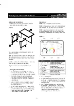
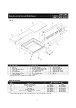
 
 
Figure 4 


Part 

Description 

Part 

Description 

Part 

Description 

Frame 

16 

Magnet Plate Base 

31 

Hook Shaft Cover 

Adjustable Platform 

17 

Heating Element Base 

 32* 

Limit Switch 

Control Switch Board 

18 

Element Radius Spacer 

33 

Arm Spring 

Sealing Arm Frame 

19 

Limit Switch Plate 

 34* 

Silicone Rubber Strip 

Right Hinge Cover 

20 

Arm Handle 

35 

M5*50 Screw 

Left Hinge Cover 

21 

Handle Rod  

36 

Spring 

Right Hinge Bracket 

22 

Handle Cap 

37 

Bushing Sleeve 

Left Hinge Bracket 

23 

Hinge/Pivot Pins 

38 

Foot 

Electromagnet Cover 

24 

Element Radius (Copper) 

39 

20x20 Cap 

10 

Side Silicone Rubber Strip Base 

25 

Magnet Plate Base Bracket 

 40* 

Transformer 

11 

Front Silicone Rubber Strip Base 

 26* 

Heating Wire Element 

 41* 

Printed Circuit Board 

12 

Sealing Aluminum Base- Side 

27 

Ceramics 

 42* 

Teflon tape 

13 

Sealing Aluminum Base- Front 

28 

Element Hook Cover 

43 

Electromagnet 

14 

Sealing wire board holder 

 29* 

Control Panel Switch Set 


15 

Magnet Plate 

30 

Element Hook 


- Denotes that the part is available as a replacement part.


Summary of Contents for 7J823

Page 1: ...Do not use this product to package flammable or combustible materials WARNING Fine powders may ignite under high temperatures even if they are not inherently combustible Test new materials under clos...

Page 2: ...24 L TYPE IMPULSE SEALER 12N411 SEALER 24 35 44 x 27 56 x 10 81 12N412 FILM BRACK 24 32 5 x 29 x 9 25 12N413 STAND 24 59 06 x 31 88 x 27 56 Sealing time is adjustable from 0 to 2 seconds Seal width is...

Page 3: ...y lifting up and to the left The table height should be set so half the package is above the sealing element and half is below The sealer table should be lower for taller packages Operation NOTE Keep...

Page 4: ...g for the film roller cradle Check screws nuts and bolts for loose connections Other Maintenance When changing the Teflon tape be sure that the entire surface under the heating element is covered with...

Page 5: ...damaged Excessively high heating timer setting Replace the printed circuit board Decrease heating timer setting Too high a setting will produce a poor seal and shorten heating element life Seal is br...

Page 6: ...6 Left Hinge Cover 21 Handle Rod 36 Spring 7 Right Hinge Bracket 22 Handle Cap 37 Bushing Sleeve 8 Left Hinge Bracket 23 Hinge Pivot Pins 38 Foot 9 Electromagnet Cover 24 Element Radius Copper 39 20x...

Page 7: ...b M8 L20 Thread 6 Carrier Adjustment Rods 13 Perf Wheel Bushing 20 M8 Foot 7 Perf Rod Bracket 14 Foam Gel Denotes that the part is available as a replacement part Replacement Parts Ref Number Descript...

Reviews: