background image

310–534

Rev. B

Supersedes Rev. A

Model 918–452

1

310–534

INSTRUCTIONS–PARTS LIST

INSTRUCTIONS

This manual contains important
warnings and information.
READ AND KEEP FOR REFERENCE.

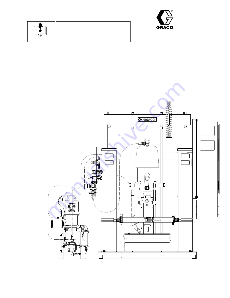
200 Liter (55 Gallon) Drum Size 
165 mm (6.5”) Dual Post

Therm-O-Flow

 55-H

Heated Supply Unit
with Hydraulic-Powered Ram

918–452

Silicone Follower Wipers, 
31:1 Bulldog

, 480 VAC, 

Therm-O-Flow Pump Module, 
Hydraulic Power Supply

918–453

Silicone Follower Wipers, 
65:1 King

, 480 VAC, 

Therm-O-Flow Pump Module, 
Hydraulic Power Supply

918–480

Silicone Follower Wipers, 
31:1 Bulldog, 240 VAC, 
Therm-O-Flow Pump Module, 
Hydraulic Power Supply

GRACO INC.   47700 HALYARD DR.  PLYMOUTH, MI

48170

COPYRIGHT 1996, GRACO INC.

Graco Inc. is registered to I.S. EN ISO 9001

Summary of Contents for Therm-O-Flow 55-H

Page 1: ...Supply Unit with Hydraulic Powered Ram 918 452 Silicone Follower Wipers 31 1 Bulldog 480 VAC Therm O Flow Pump Module Hydraulic Power Supply 918 453 Silicone Follower Wipers 65 1 King 480 VAC Therm O Flow Pump Module Hydraulic Power Supply 918 480 Silicone Follower Wipers 31 1 Bulldog 240 VAC Therm O Flow Pump Module Hydraulic Power Supply GRACO INC 47700 HALYARD DR PLYMOUTH MI 48170 COPYRIGHT 199...

Page 2: ... Unit 34 Servicing the Follower 35 Removing Re installing the Pump from the Ram 37 Separating the Pump from the Air Motor 38 Re attaching the Air Motor to the Pump 38 Removing the Follower from the Pump 38 For 240 VAC Supply Units 39 For 480 575 VAC Supply Units 40 Inspection Frequency 41 Parts 43 Model 918 452 480 Vac 918 480 240 Vac 43 Model 918 453 Therm O Flow 480 Vac 45 Model 918 510 Hydrauli...

Page 3: ...aximum inbound hydraulic pressure to the ram D Do not exceed 0 7 MPa 7 bar 100 psi maximum inbound air pressure to the material pump D Never exceed the recommended working pressure or the maximum air inlet pressure stated on your pump or in the Technical Data on page 75 D Be sure that all spray dispensing equipment and accessories are rated to withstand the maxi mum working pressure of the pump Do...

Page 4: ...ry D Fluid injected into the skin might look like just a cut but it is a serious injury Get immediate medical attention D Do not point the gun valve at anyone or at any part of the body D Do not put your hand or fingers over the spray tip nozzle D Do not stop or deflect fluid leaks with your hand body glove or rag D Always have the trigger guard on the gun when dispensing D Check the gun diffuser ...

Page 5: ...ipment is installed and operated in compliance with applicable codes D Make sure power is disconnected when servicing and repairing equipment D Have any checks installation or service to electrical equipment performed by a qualified electri cian only D Never exceed the maximum wattage of the supply unit See the wiring diagrams in this manual for more information D Only use hoses that have a maximu...

Page 6: ...w the specific hazards of the fluid you are using D Store hazardous fluid in an approved container Dispose of hazardous fluid according to all local state and national guidelines D Always wear protective eyewear gloves clothing and respirator as recommended by the fluid and solvent manufacturer D Avoid exposure to heated material fumes D Provide adequate ventilation ...

Page 7: ...tor J Pump Mounting Bracket K Fluid Regulator compensator L Heated Hose M Hose Hanger N Follower Blow off Valve O Ram Air Regulators P Follower Rod Q Pump Assembly R Ram Hand Valve S Ram Module T Automatic Dispense Valve U Heated Follower Plate Assembly V Wipers W Drum Clamp X Hydraulic Power Supply Fig 1 Therm O Flow Supply Unit Model 918 452 shown with Hydraulic Powered Ram Module 918 420 Hoses ...

Page 8: ...nel D Locate the hydraulic power supply in an area that has easy access for servicing and adjust ing the hydraulic pressure on the supply unit has sufficient clearance for the hydraulic lines that you will attach to the pump will allow you to easily read the hydraulic fluid level gauge 2 Make sure that you will be able to level the base of the ram using metal shims 3 When you bolt the ram to the f...

Page 9: ... type master air valve D Ram Air Regulators O control the air pressure to the hydraulic power supply that controls ram move ment There are separate air regulators to control the ram pressure in the up and down directions D Hydraulic Power Supply X controls the ram s movement D Follower Blow off Valve N controls the air pres sure to the follower blow off D FRL filter regulator lubricator A D and I ...

Page 10: ...g Fig 36 on page 72 for ram mounting and clearance dimensions See the hydraulic power supply dimensions drawing Fig 37 on page 73 for hydraulic power supply clearance dimen sions Electrically Connect Hoses to the Electrical Control Panel WARNING FIRE HAZARD Only use hoses that have a maximum wattage less than or equal to 1250 watts Using hoses with higher maximum wattage could create a runaway tem...

Page 11: ...yed and all other spraying dispensing equip ment used or located in the spraying dispensing area Check your local electrical code for detailed grounding instructions for your area and type of equipment Hydraulic Power Supply Follow the instructions in Form 310 533 for grounding the hydraulic power supply Air and Fluid Hoses Use electrically conductive hoses only Dispensing Spray Gun Follow the dis...

Page 12: ... 34 6 For information about specific terminal locations and connections see the wiring diagrams on these pages Model VAC Pages C32428 240 60 64 C32429 480 66 70 To connect the control panel to the electrical source 1 Create an opening in the control panel s housing for the conduit that will enclose the wire from the facility s power source 2 Thread the wire from the power source into the control p...

Page 13: ...ntrollers for each of the heated zones To check sensor resis tance 1 Make sure the power is off and that the disconnect switch is in the OFF position 2 Make electrical resistance checks for the compo nents listed below See the appropriate wiring diagrams Model VAC Pages C32428 240 60 64 C32429 480 66 70 3 Replace any parts whose resistance readings do not comply with the ranges listed in the chart...

Page 14: ...es listed in the chart below NOTE Check resistance at ambient room tempera ture 63_ 77_ F Heaters Value Range Zone Component Terminals 240 VAC 480 VAC 1 Follower 3L1 3L2 12 8 ohms 1 3 ohms 25 5 ohms 2 6 ohms 1 Follower 3L1 3L2 3L2 3L3 3L3 3L1 12 8 ohms 1 3 ohms 25 5 ohms 2 6 ohms 3 3 3 3L3 3L1 2 Dispense Hose 1 2002 1092 See Technical Data supplied w Hose See Technical Data supplied w Hose 3 Dispe...

Page 15: ...nal Switch Factory Settings Each temperature controller has internal switches to control some of its operational characteristics The switches are only accessible if you remove the control ler from the electrical control panel The factory set tings should satisfy most application needs For information about changing the settings see the temperature controller instruction sheet included in the elect...

Page 16: ...t using the temperature controls see the literature that came with the electrical control panel Configuring Temperature Controllers for Unused Zones If your electrical control panel has more temperature controllers than are needed for your current applica tion a qualified electrician must disconnect the un used temperature controllers CAUTION If the unused controllers are not disconnected the supp...

Page 17: ...ct switch is in the OFF position 2 Open the electrical control panel The temperature controller mounting holes are located in the door of the control panel 3 For each unused temperature controller Fig 8 a Disconnect the power wire wire 1162 in the number 9 position on the back of the tempera ture controller b Maintain the integrity of the electrical connec tions by connecting the jumper wire to th...

Page 18: ...e hydraulic pressure For more informa tion see Form 310 533 5 Raise the ram using the following procedure a Close all air regulators b Move the ram hand valve lever to the UP posi tion c Slowly open the air regulators until the ram starts to move upwards Do not apply more than 0 7 MPa 7 bar 100 psi inbound air pressure to the hydraulic supply If the ram does not move in the expected direction chec...

Page 19: ...ntation 1 Raise the follower plate high enough to put a drum of material under it Make sure the drum clamp stays clear of the follower assembly 2 Open the drum clamp 3 Open a drum of the proper material and place it under the elevated follower plate NOTE Whenever drum changes are required remove the cover from a drum of new material by holding it level and lifting it straight up Tipping the cover ...

Page 20: ...essures can cause serious per sonal injury Be sure to open the dis pense valve during system heat up to alleviate pressure which might occur in the system due to material expansion 1 Lock the gun valve trigger safety 2 Shut off the main air supply to the material pump 3 Close all air bleed valves 4 Unlock the gun valve trigger safety 5 Hold a metal part of the gun valve firmly to the side of a gro...

Page 21: ... is ON 2 Turn the CONTROL ON switch to ON 3 Open the dispense valve over a waste container to allow the material to expand This will prevent damage to the equipment 4 Make sure that all dispense valves are open WARNING HOT PRESSURIZED FLUID HAZARD Make sure to open the dispense valve to reduce risk of pressurized fluid leaks because of thermal expansion of the fluid during system heat up To reduce...

Page 22: ...TO 2 Turn the HEAT switch 8 on the electrical control panel to ON WARNING To reduce the risk of serious injury whenever you are instructed to relieve pressure always follow the Pressure Relief Procedure page 20 3 Relieve the supply unit pressure 4 Leave the dispense valve open and over an empty waste container to relieve pressure that could build up while the system is heating 5 Make sure that all...

Page 23: ...mage to the follower wipers may result CAUTION Do not raise the ram and remove the follower plate from the empty drum unless the supply unit is at full operating temperature Drum changes can only be performed when the system is heated Attempting to change a drum when the supply unit is cold could result in injury or damage to the equipment An empty drum clamp can interfere with up and down operati...

Page 24: ...e drum position as the follower low ers If necessary stop lowering the follower before contacting the drum and adjust the drum and or clamp positions to align the drum with the follower plate c Continue lowering the follower As the follower enters the drum loosen the air bleed stick Loosening the bleed stick allows trapped air between the follower plate and the top of the material to escape d When...

Page 25: ... to relieve pressure always follow the Pressure Relief Procedure page 20 3 Open dispense guns or valves over an empty waste container 4 Relieve the pressure Emergency Stop 1 On the electrical control panel Fig 11 a Turn the CONTROL ON switch 7 to OFF b Turn OFF the main electrical disconnect 9 Fig 11 7 9 2 Stop the pump by closing the Pump s Bleed type Master Air Valve closest to the motor s air i...

Page 26: ...On ON The CONTROL ON switch 7 is set to either the ON or AUTO position and power is being supplied to the electrical control panel components OFF The CONTROL ON switch 7 is set to the OFF position 10 High Temperature Alarm ON The temperature of any of the heated components is out of range and the power to all heated components is inter rupted For more information see the Temperature Out of Range s...

Page 27: ...t 4 Wait until all components in the supply unit have returned to operating temperature 5 Close dispense valves 6 Turn on pump air 7 Resume operation Resetting the Ground Fault Interrupt This control panel is equipped with a ground fault interrupt GFI circuit breaker Fig 15 If the discon nect switch is ON but all lights on the electrical control panel are off have a qualified electrician check the...

Page 28: ... drums are properly grounded Refer to Ground The System on page 11 WARNING To reduce the risk of serious injury whenever you are instructed to relieve pressure always follow the Pressure Relief Procedure page 20 2 Relieve the pressure PRESSURIZED FLUID HAZARD Always use the lowest possible fluid pressure and maintain firm metal to metal contact between the gun valve and the drum during flushing to...

Page 29: ...d Worn rod seal Replace o rings in guide sleeve See Form 310 533 Fluid squeezes past follower plate wipers Ram pressure too high Decrease ram pressure q p plate wipers Worn or damaged wipers Replace wipers See procedure in the Supply Unit documentation Material pump won t prime properly or pumps air Closed main air valve or clogged air line Open air valve clear air line p p p properly or pumps air...

Page 30: ...ve clear air line down or push plate up Not enough ram pressure Increase ram pressure Hydraulic valve passage clogged Replace hydraulic valve See Form 310 533 Worn ram piston seal Replace ram piston seal Ram moves in opposite direction than expected Incorrectly connected hydraulic lines or incorrectly connected air lines Connect hydraulic or air lines to their correct connectors See Form 310 533 ...

Page 31: ...6 Turn air on to the pump and set the pump air regulator for normal opera tion Downstroke Lower check in pump is worn Upstroke Upper check in pump is worn Rebuild and replace pump as neces sary Material leaks around pump outlet Outlet fitting is loose Tighten outlet fitting Material leaks around bleed port Bleed port fitting is loose Tighten bleed port fitting Pump won t move up or down Problem wi...

Page 32: ...ir continually exhausting around air motor shaft Air motor shaft seal is damaged Replace air motor shaft seal Air continually exhausting around the air valve slide valve Air valve slide valve gasket is damaged Replace the valve gasket Air continually exhausting from muffler while the motor is idle Internal seal damage Rebuild air motor Oil leaking from exhaust port Too much lubricant mixed in with...

Page 33: ...ply unit automatically turns off power to supply unit components Unit turns power back on when overheated components reach ap propriate temperatures Heat is turned off after a period of pump inactivity Pump has not moved within the pro grammed time period and the inactivity timer has been triggered See procedure on page 27 High Temperature Alarm indicator is lit before the unit has heated up One o...

Page 34: ... panel set the ram regulator pressure for D RAM UP to 0 zero D RAM DOWN to 0 zero 5 Exhaust pressure from both sides of the ram a Move the ram hand valve lever to the DOWN position until all hydraulic pressure is ex hausted from one side of the ram b Move the ram hand valve lever to the UP position until all hydraulic pressure is ex hausted from the other side of the ram 6 Close the master air loc...

Page 35: ...e the follower plate up out of the drum by observing the cautions and warnings then follow ing steps 1 through 4 of the procedure for Chang ing Empty Drums on page 23 2 Separate the wiper butt joint and bend back the strapping that covers the clamp Loosen the clamp by unscrewing the worm gear then remove the wiper 3 Thread the strapping through the new wiper 4 Install the wiper on the follower pla...

Page 36: ...of injury or damage to equipment make sure the main discon nect is OFF before continuing with this procedure 3 Turn the system CONTROL ON switch to OFF 4 Turn OFF the main electrical disconnect 5 Loosen the conduit locknut 120 6 Remove the sensor 90 from the follower plate 7 Loosen the cord grip 100 located under the junc tion box 8 Remove the junction box s cover 9 Disconnect the 2 sensor wires f...

Page 37: ...njury or damage to equipment make sure the main discon nect is OFF before continuing with this procedure 7 Bleed off pressure in the system and excess material by opening the dispense gun and catching the material in a waste container 8 On the electrical control panel turn the system CONTROL ON switch to OFF 9 Disconnect all material hoses 10 RTV sealant on the pump shroud may make it difficult to...

Page 38: ... above procedure to re attach the pump to the air motor Be sure that D when you reinsert the collar couplings 30 into the coupling nut the large flanges point upwards D you re apply RTV sealant to the pump shrouds before re assembling them For more information see Form 310 530 or call your Graco technical support representative Removing the Follower from the Pump See Figs 33 and 34 on pages 56 and...

Page 39: ...39 310 534 Service Fig 21 1391 1401 1321 1331 1791 1841 To Ram Junction Box For 240 VAC Supply Units ...

Page 40: ...40 310 534 Service Fig 22 1391 1401 1321 1331 1791 1841 To Ram Junction Box For 480 575 VAC Supply Units ...

Page 41: ...worn parts Pump See the material pump s instructions for its inspection frequency Ground Fault Interrupt Periodically once a month test the ground fault interrupt switch by pushing the TEST button See the literature that came with the electrical control panel for more information Hydraulic Power Supply Once a month check the hydraulic fluid level Add more fluid if necessary See the Service section...

Page 42: ...42 310 534 Notes ...

Page 43: ...005 Label warning hot surface 2 120 208356 Motor Bulldog Air 7 See 307 049 for parts 1 130 C03510 Kit Pump Air motor mounting 1 Ref No Part No Description Qty 140 C03508 Pump HCM 800 assy 480 575 Vac See 310 530 308 570 and 307 765 for parts 1 C03511 Pump HCM 800 assy 240 Vac See 310 530 308 570 and 307 765 1 150 918395 Clamp H D drum 200 liter 55 gal 2 160 C32434 Kit follower rod mounting 1 170 C...

Page 44: ...120 100 110 60 50 10 1 2 npt Air Inlet Specifications Pump Air supply 0 7 MPa 7 bar 100 psi Pump 60 Cycles Min Max 2 80 m3 min 100 scfm Max Fluid Working Pressure 2 17 MPa 217 bar 3100 psi max Floor Space Dimensions 1503 68 mm 59 2 Wide x 739 14 mm 29 1 Deep Approx Weight 544 kg 1200 lbs 230 Model 918 452 918 480 Volts 480 3 phase 240 3 phase Full Load Amps 34 6 69 1 ...

Page 45: ...Label warning hot surface 2 120 207647 Motor King Air 10 See 306 968 and 307 255 for parts 1 130 C03510 Kit Pump Air motor mounting 1 Ref No Part No Description Qty 140 C03508 Pump HCM 800 assy 480 575 Vac See 310 530 308 570 and 307 765 for parts 1 150 918395 Clamp H D drum 200 liter 55 gal 2 160 C32434 Kit follower rod mounting 1 170 C31008 Kit silicone rubber follower wiper 200 liter 55 gal 1 1...

Page 46: ...0 130 120 100 110 60 50 1 2 npt Air Inlet 10 230 Specifications Pump Air supply 0 6 MPa 6 bar 90 psi Pump 50 Cycles Min Max 4 2 m3 min 150 scfm max Max Fluid Working Pressure 4 06 MPa 406 bar 5850 psi max Voltage 480 3 phase Full Load Amps 34 6 Floor Space Dimensions 1503 68 mm 59 2 Wide x 739 14 mm 29 1 Deep Approx Weight 544 kg 1200 lbs ...

Page 47: ... 1 160 C20712 Rivet 2 170 150707 Plate designation 1 180 517435 Valve 4 way hydraulic 1 2 npt 1 Ref No Part No Description Qty 190 C19388 Elbow swivel 1 4t x 1 8p 2 200 C38211 Elbow swivel 3 8t x 1 2p 1 210 C20470 Nipple reducing hex 1 2 npt x 1 4 npt 1 220 C20769 Adapter male 7 8 37 x 3 8p 3 230 C20768 Adapter male 7 8 37 x 1 2p 3 240 517446 Filter air 1 2 npt 1 250 C19391 Elbow male 1 4t x 1 4p ...

Page 48: ... Model 918 510 Hydraulic Power Supply 120 130 140 150 160 170 180 190 320 200 240 250 260 270 60 280 290 300 60 10 60 30 40 50 60 70 80 90 230 80 20 110 opposite side 250 350 360 370 230 220 100 220 220 310 210 230 330 20 340 ...

Page 49: ... 5080 mm 200 240 C11029 Regulator air 1 250 C19395 Elbow connector 1 4p x 3 8t 4 260 C19445 Elbow street 1 4 npt 1 Ref No Part No Description Qty 270 C06015 Valve hand 1 4 npt 1 280 C38260 Tee run male 1 4p x 3 8t 2 290 C38261 Tee run male 3 8p x 3 8 t 1 300 C07585 Gauge air pressure 160 psi 11 bar 1 1 MPa 2 310 C20350 Elbow connector female 1 4p 1 4t 2 320 C11057 Regulator air 2 330 C19394 Elbow ...

Page 50: ... 50 60 70 80 90 100 120 140 150 120 170 210 200 220 180 190 200 230 240 250 200 250 20 280 290 300 320 200 330 300 310 320 340 250 350 370 340 380 320 340 390 110 130 130 200 270 260 310 230 340 360 1 2 npt Air Inlet L O VLV REG 1 UP VLV 1 DOWN AIR MOTOR REG 2 REG 3 RAM UP RAM DOWN 3 1 PRESIDENT PUMP FOLLOWER BLOW OFF VLV 3 FOLLOWER BLOW OFF REG 4 40 160 510 400 ...

Page 51: ... Clamp cylinder 4 20 C19124 Screw hex head 3 8 16 x 1 4 30 918421 Clamp back half assy 1 40 918423 Kit hinged front drum clamp 1 Ref No Part No Description Qty 50 617394 Pin quick release 2 60 C19213 Washer lock 3 8 4 70 C19200 Washer flat 3 8 4 80 617433 Spacer 4 Fig 29 10 80 70 60 20 30 40 50 ...

Page 52: ...t Ref No Part No Description Qty 10 C32402 Rod follower hot 2 20 161822 Plate motor mounting 2 30 100672 Screw set 3 8 16 unc x 1 4 Ref No Part No Description Qty 40 C19206 Washer lock for 3 4 2 50 C19187 Nut hex 3 4 10 unc 2 Fig 30 10 20 30 40 50 ...

Page 53: ...90000 Rod stand off 3 Ref No Part No Description Qty 30 184129 Collar coupling 2 40 186925 Nut coupling 1 C03509 Therm O Flow Pump Module 200 liter 55 gal ref See Form 310 530 for more information Fig 31 10 20 30 40 1 2 207647 King Air Motor ref Notes Torque to 81 89 N m 60 66 ft lb Torque to 196 210 N m 145 155 ft lb 1 2 ...

Page 54: ...od middle 1 30 C32446 Bracket vent hood side 2 40 C32444 Bolt U square bend 3 50 C19815 Washer lock 3 8 6 Ref No Part No Description Qty 60 C19092 Screw hex hd 1 4 20 x 7 8 lg 6 70 C19198 Washer flat 1 4 12 80 C19209 Washer lock 1 4 6 90 C19189 Nut hex 1 4 20 6 100 C14038 Label not shown 1 Fig 32 30 10 40 50 20 90 SECTION A A A A 80 70 60 ...

Page 55: ...32386 Wire hi temp 10 ga 13 m 515 150 C19286 Nut hex 10 32 unf 24 160 C32201 Gasket 1 170 C19340 Nipple short 1 2 npt 1 180 C19506 Coupling 1 2 npt 1 Ref No Part No Description Qty 190 617227 Handle bleed 1 200 207440 Valve dispense See 306 715 for parts 1 210 C19254 Plug pipe 1 4 npt not shown 1 220 C19258 Plug pipe 1 2 npt 6 230 C19213 Washer lock 0 8 6 240 C19846 Screw soc hd cap 3 8 16 x 2 5 6...

Page 56: ...pers not included See Accessories section on page 71 for ordering information 80 50 10 20 30 40 60 50 120 110 100 90 150 140 130 160 60 50 170 250 180 260 190 280 270 300 290 200 220 240 230 70 80 320 Notes 203 mm 8 533 mm 21 1 2 2 1 Front Rear 1321 1331 Wiring Heaters to the Junction Box ...

Page 57: ... C32387 Wire hi temp 8 ga 13 m 515 150 C19286 Nut hex 10 32 unf 24 160 C32201 Gasket 1 170 C19340 Nipple short 1 2 npt 1 Ref No Part No Description Qty 180 C19506 Coupling 1 2 npt 1 190 617227 Handle bleed 1 200 207440 Valve dispense 1 210 C19254 Plug pipe 1 4 npt not shown 1 220 C19258 Plug pipe 1 2 npt 6 230 C19213 Washer lock 0 8 6 240 C19846 Screw soc hd cap 3 8 16 x 2 5 6 250 517414 Reducer h...

Page 58: ...Wipers not included See Accessories section on page 71 for ordering information 80 50 10 20 30 40 60 50 120 110 100 90 150 140 130 160 60 50 170 250 180 260 190 280 270 300 290 200 220 240 230 70 80 320 Notes 203 mm 8 610 mm 24 1 2 2 1 1321 1331 Wiring Heaters to the Junction Box ...

Page 59: ... Terminals 3L1 3L2 3L3 5L1 5L2 GND GND 1091 1092 9 Total Type 1492 CD2 40 Terminals 1322 1341 1391 1392 1401 1411 1521 1522 1531 1541 1591 1592 1601 1611 1661 1662 1671 1681 1731 1732 1741 1751 Spare 1771 1791 1792 2002 2022 2042 2062 3 Spare 40 Total Type 1492 CA1 Inactivity Timer Optional Ground Fault Interrupt Spare Parts Part Number Temperature Controller C07631 Solid State Relay for SSRs 152 ...

Page 60: ... 310 534 Electrical Control Panel and Wiring for C32428 240 VAC Lines 100 121 122 122 ...

Page 61: ...310 534 61 Electrical Control Panel and Wiring for C32428 Lines 122 142 121 121 TEMPERATURE CONTROL TEMPERATURE CONTROL ...

Page 62: ...62 310 534 Electrical Control Panel and Wiring for C32428 240 VAC Lines 150 169 170 170 TEMPERATURE CONTROL TEMPERATURE CONTROL TEMPERATURE CONTROL ...

Page 63: ...310 534 63 Electrical Control Panel and Wiring for C32428 Lines 170 192 169 169 TEMPERATURE CONTROL Remove jumper if PUMP INACTIVITY TIMER is used ...

Page 64: ...64 310 534 Electrical Control Panel and Wiring for C32428 240 VAC Lines 200 220 ...

Page 65: ...310 534 65 Notes ...

Page 66: ... 310 534 Electrical Control Panel and Wiring for C32429 480 VAC 122 122 Lines 100 121 ...

Page 67: ...310 534 67 121 121 Electrical Control Panel and Wiring for C32429 Lines 122 142 TEMPERATURE CONTROL TEMPERATURE CONTROL ...

Page 68: ...68 310 534 170 170 Electrical Control Panel and Wiring for C32429 480 VAC Lines 150 169 TEMPERATURE CONTROL TEMPERATURE CONTROL TEMPERATURE CONTROL ...

Page 69: ...310 534 69 169 169 Electrical Control Panel and Wiring for C32429 Lines 170 192 TEMPERATURE CONTROL Remove jumper if PUMP INACTIVITY TIMER is used ...

Page 70: ...70 310 534 Electrical Control Panel and Wiring for C32429 480 VAC Lines 200 220 ...

Page 71: ... material adhesion may be a problem 918 395 LOW LEVEL DRUM KIT Lights a red beacon signal when the drum is empty 918 394 PUMP MOUNTING KIT Used to secure pump assembly to ram Includes follower rods and brackets C32434 PUMP AIR MOTOR MOUNTING KIT Used in heated applications to connect the heated Check Mate 800 pump to Bulldog and Senator air motors C03510 HOSE SUPPORT KIT Supports hose to ram to pr...

Page 72: ...0 534 72 Dimensions Fig 36 Ram Mounting and Clearance Dimensions 1168 mm 48 in 1067 mm 42 in 737 mm 29 in 635 mm 25 in 533 mm 21 in 1808 mm 71 in 2824 mm 111 in 693 mm 27 3 in 1151 mm 45 3 in 937 mm 37 in ...

Page 73: ...310 534 73 Dimensions Fig 37 Hydraulic Power Supply Mounting and Clearance Dimensions 551 mm 21 7 335 mm 13 2 292 mm 11 5 432 mm 17 0 279 mm 11 0 229 mm 9 0 785 mm 30 9 330 mm 13 0 ...

Page 74: ...310 534 74 Dimensions Fig 38 Electrical Control Panel Mounting and Clearance Dimensions 254 mm 10 1189 mm 46 8 945 mm 37 25 493 mm 19 4 646 mm 25 4 ...

Page 75: ...x 1 04 m deep 63 8 x 40 9 Overall height ram lowered 1808 mm 71 2 Overall height ram extended 2824 mm 111 2 Floor space hydraulic power supply 465 mm x 432 mm deep 18 3 x 17 Overall height hydraulic power supply 785 mm 30 9 Material pump air inlet Senator Bulldog pumps President pumps 3 4 nps m 1 2 npt Hydraulic power supply air inlet 3 8 o d tube fitting Fluid outlet 1 npt f Sound Data See indivi...

Page 76: ... above The buyer agrees that no other remedy including but not limited to incidental or consequential damages for lost profits lost sales injury to person or prop erty or any other incidental or consequential loss shall be available Any action for breach of warranty must be brought within two 2 years of the date of sale GRACO MAKES NO WARRANTY AND DISCLAIMS ALL IMPLIED WARRANTIES OF MERCHANTABILIT...

Reviews: