background image

Setup 

22

309551C

Turn main power switch OFF 

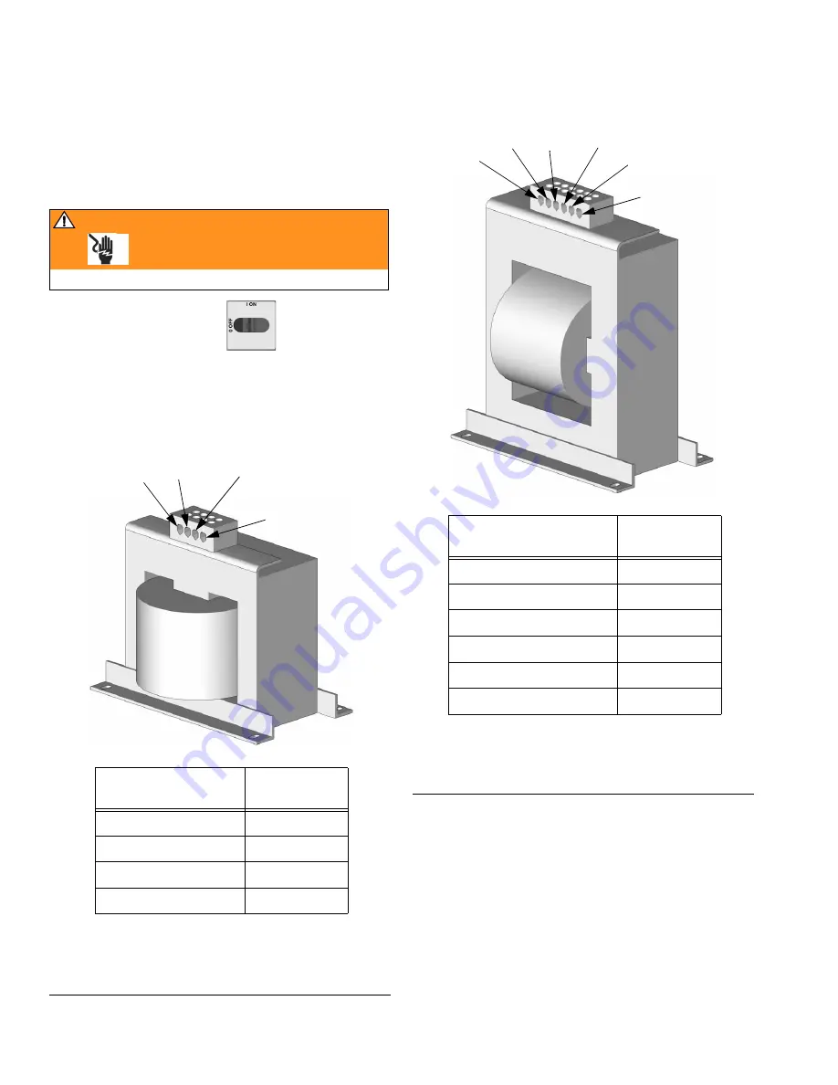
. Transformer tap 

wire connections vary depending on length of heated 
hose. See F

IG

. 7 and F

IG

. 8. Verify that tap wire connec-

tions are correct.

11.

Set transformer wire 
taps

WARNING

Read warnings, page 5.

F

IG

. 7: Model E-20 and E-XP1 Transformer Wire Taps

.

* Length includes heated fluid hose and whip hose.

Hose Length* ft (m)

Tap Terminal 

Label (ft)

60-85 (18.3-25.9)

50

110-135 (33.5-41.2)

100

160-185 (48.8-56.4)

150

210-235 (64.1-71.7)

200

TI3469a

50 ft

100 ft

150 ft

200 ft

F

IG

. 8: Model E-30 and E-XP2 Transformer Wire Taps

* Length includes heated fluid hose and whip hose.

Hose Length* ft (m)

Tap Terminal 

Label (ft)

60-85 (18.3-25.9)

50

110-135 (33.5-41.2)

100

160-185 (48.8-56.4)

150

210-235 (64.1-71.7)

200

260-285 (79.3-86.9)

250

310 (94.6)

300

TI3470a

50 ft

100 ft

150 ft

200 ft

250 ft

300 ft

Summary of Contents for Series E

Page 1: ...441 Copyright 2003 Graco Inc is registered to I S EN ISO 9001 309551C Operation Electric Heated Plural Component Proportioner For spraying polyurethane foam and polyurea coatings Not for use in explosive atmospheres See Models on page 3 TI3764a 1 ...

Page 2: ...ed pumps 18 Connect pressure relief lines 18 Install Fluid Temperature Sensor FTS 19 Connect heated hose 20 Close gun fluid manifold valves A and B 21 Connect whip hose to gun fluid manifold 21 Pressure check hose 21 Set transformer wire taps 22 Ground system 23 Supply wet cups with Throat Seal Liquid 24 Startup 25 Load fluid with feed pumps 25 Set temperatures 26 Set pressure 27 Spraying 28 Shutd...

Page 3: ...14 140 246034 C E 20 230V 3 6 000 20 9 0104 0395 2000 14 140 246035 B E 30 230V 3 10 200 30 13 5 0272 0 1034 2000 14 140 Part No Series Model Voltage phase Heater Watts Flow gpm lpm Output per Cycle A B gal liter Maximum Fluid Working Pressure psi MPa bar 246024 B E XP1 230V 1 10 200 1 3 8 0104 0395 2500 17 2 172 246028 B E XP2 230V 1 15 300 2 7 6 0203 0771 3500 24 1 241 246029 B E XP1 380V 3 10 2...

Page 4: ...20 230V 1 phase 309727 Electrical Diagrams E XP2 and E 30 230V 1 phase 309728 Electrical Diagrams E XP1 and E 20 380V 3 phase 309729 Electrical Diagrams E XP2 and E 30 380V 3 phase 309730 Electrical Diagrams E XP1 and E 20 230V 3 phase 309731 Electrical Diagrams E XP2 and E 30 230V 3 phase Reactor Data Reporting Kit Part No Description 309867 Instruction Manual English Fusion Spray Gun Part No Des...

Page 5: ...K HAZARD Solvent and fumes in work area can ignite or explode High voltage components can cause electric shock To help prevent fire explosion and electric shock Shut off main power switch and wait 5 minutes before opening Reactor cabinet door All electrical wiring must be done by trained and qualified personnel and comply with all local codes Ground equipment and conductive objects See Ground syst...

Page 6: ... with all applicable safety regulations BURN HAZARD This equipment is used with heated fluid which can cause equipment surfaces to become very hot To avoid severe burns Do not touch hot fluid or equipment Allow equipment to cool completely before touching it Wear gloves if fluid temperature exceeds 110 F 43 C TOXIC FLUID OR FUMES HAZARD Toxic fluids or fumes can cause serious injury or death if sp...

Page 7: ... Sensor FTS D Heated Whip Hose E Fusion Spray Gun F Gun Air Supply Hose G Air Supply Lines J Fluid Supply Lines K Feed Pumps L Agitator M Desiccant Dryer P Gun Fluid Manifold Q Air Filter Separator R Return Lines FIG 1 Typical Installation with circulation A B C D E F G J K L M G J K TI2765A R P Q R Shown exposed for clarity Wrap with tape during operation ...

Page 8: ...FTS D Heated Whip Hose E Fusion Spray Gun F Gun Air Supply Hose G Air Supply Lines H Waste Containers J Fluid Supply Lines K Feed Pumps L Agitator M Desiccant Dryer N Bleed Lines P Gun Fluid Manifold Q Air Filter Separator FIG 2 Typical Installation without circulation A B C D E F G H J K L M G J K TI2510A N P Shown exposed for clarity Wrap with tape during operation Q ...

Page 9: ... Valve SB Component B PRESSURE RELIEF SPRAY Valve TA Component A Pressure Transducer behind gauge GA TB Component B Pressure Transducer behind gauge GB DG Drive Gear Housing EC Electrical Cord Strain Relief EM Electric Motor FH Fluid Heaters behind shroud FM Reactor Fluid Manifold FV Fluid Inlet Valve B side shown HC Heated Hose Electrical Connector MC Motor Control Display MP Main Power Switch RS...

Page 10: ...rs FIG 4 Temperature Controls and Indicators F C A B Zone A Arrow Keys Zone B Arrow Keys Hose Zone Arrow Keys Temperature Scale Keys Heater A On Off Key Heater Power Indicators Target Temperature Key Actual Temperature Key Heater Displays Hose Heater On Off Key Heater B On Off Key ...

Page 11: ...f Also clears heater zone diagnostic codes see page 35 LEDs are on steady when heater zones are powering up Begin flashing as heat reaches targets Temperature Arrow Keys Press then press or to adjust tem perature settings in 1 degree increments Temperature Displays Show actual temperature or target temperature of heater zones depending on selected mode Defaults to actual at startup Range is 32 190...

Page 12: ... Indicators 12 309551C Motor Controls and Indicators FIG 5 Motor Controls and Indicators PSI BAR ON OFF PARK Pressure Arrow Keys PSI BAR Keys Cycle Count Key Pressure Cycle Display Pressure Key Motor ON OFF Key PARK Key ...

Page 13: ...ure scale Pressure Key LED Press to display fluid pressure Cycle Count Key LED Press to display cycle count Pressure Arrow Keys Press or to adjust fluid pressure when motor is ON Setpoint displays for 10 sec When motor is OFF pressing will enter jog mode To exit jog mode press until display shows dashes or current pressure Pressure Cycle Display Shows fluid pressure or cycle count depending on mod...

Page 14: ...Motor Controls and Indicators 14 309551C ...

Page 15: ...oisture proof rubber compounds Never use reclaimed solvents which may contain moisture Always keep solvent containers closed when not in use Always park component A pump when you shut down see page 13 Spray Adjustments Flow rate atomization and amount of overspray are affected by four variables Fluid pressure setting Too little pressure results in an uneven pattern coarse droplet size low flow and...

Page 16: ...s access to parts which may cause electric shock or other serious injury if work is not performed properly Have a qualified electrician connect power and ground to main power switch terminals see page 17 Be sure your installa tion complies with all National State and Local safety and fire codes Table 1 Electrical Requirements kW Full Load Amps E SERIES Part No Model Voltage phase Full Load Peak Am...

Page 17: ...ire ground 246033 E XP1 8 8 4 3 wire ground 246034 E 20 10 5 3 3 wire ground 246035 E 30 8 8 4 3 wire ground 246036 E XP2 6 13 3 3 wire ground WARNING Read warnings page 5 a 230V 1 phase Using 5 32 or 4 mm hex allen wrench connect two power leads to L1 and L2 Connect green to ground GND L1 L2 GND TI2515A b 230V 3 phase Using 5 32 or 4 mm hex allen wrench connect three power leads to L1 L2 and L3 C...

Page 18: ...hutoffs downstream of the PRESSURE RELIEF SPRAY valve outlets BA BB The valves function as overpressure relief valves when set to SPRAY Lines must be open so valves can automati cally relieve pressure when machine is operating If circulating fluid back to the supply drums use high pressure hose rated to withstand the maximum work ing pressure of this equipment a Recommended Connect high pres sure ...

Page 19: ...refully extend FTS probe S Do not bend or kink probe Insert in component A ISO side of main hose B b Connect FTS C to whip hose D c Connect whip hose ground wire U to ground screw on underside of FTS d Connect main hose B to FTS C e Connect electrical connectors V Secure connections with plastic ties W f Connect air hose F to whip air hose X g Connect main hose cable Y to FTS Slide insulator sleev...

Page 20: ...nd B out lets on Reactor fluid manifold FM Hoses are color coded red for compo nent A ISO blue for component B RES Fittings are sized to prevent con nection errors Manifold hose adapters N P allow use of 1 4 in and 3 8 in ID fluid hoses To use 1 2 in 13 mm ID fluid hoses remove adapters from fluid mani fold and install as needed to connect whip hose d Connect cables Y Connect electrical connectors...

Page 21: ...ld valves A and B TI2411A 9 Connect whip hose to gun fluid manifold Do not connect manifold to gun 10 Pressure check hose See hose manual Pressure check for leaks If no leaks wrap hose and electrical connections to protect from damage TI2417A ...

Page 22: ...ludes heated fluid hose and whip hose Hose Length ft m Tap Terminal Label ft 60 85 18 3 25 9 50 110 135 33 5 41 2 100 160 185 48 8 56 4 150 210 235 64 1 71 7 200 TI3469a 50 ft 100 ft 150 ft 200 ft FIG 8 Model E 30 and E XP2 Transformer Wire Taps Length includes heated fluid hose and whip hose Hose Length ft m Tap Terminal Label ft 60 85 18 3 25 9 50 110 135 33 5 41 2 100 160 185 48 8 56 4 150 210 ...

Page 23: ...r local code d Object being sprayed follow your local code e Solvent pails used when flushing follow your local code Use only metal pails which are conductive placed on a grounded surface Do not place pail on a nonconductive surface such as paper or cardboard which interrupts ground ing continuity f To maintain grounding continuity when flushing or relieving pressure hold a metal part of spray gun...

Page 24: ...cup a Component A ISO Pump Keep res ervoir R filled with Graco Throat Seal Liquid TSL Part No 206995 Wet cup piston circulates TSL through wet cup to carry away isocyanate film on dis placement rod R TI3765a 2 b Component B Resin Pump Check felt washers in packing nut wet cup R daily Keep saturated with Graco Throat Seal Liquid TSL Part No 206995 to prevent material from hardening on dis placement...

Page 25: ...p steps 1 13 are com plete pages 16 24 b Turn on component B agitator if used c Turn both PRESSURE RELIEF SPRAY valves SA SB to SPRAY TI2482A SA SB d Open fluid inlet valves FV e Start feed pumps WARNING Always provide two grounded waste containers to keep component A and component B fluids separate f Hold gun fluid manifold over two grounded waste containers Open fluid valves A and B until clean ...

Page 26: ...r and zones F C A B For zone only if FTS is disconnected at startup display will show hose current 0A See step h page 27 e Press to display actual tempera tures WARNING Read warnings page 5 Do not turn on hose heat without fluid in hoses f Turn on heat zone by pressing Preheat hose 15 60 min Indi cator will flash very slowly when fluid reaches target temperature Display shows actual fluid temperat...

Page 27: ...rrent with key h Manual current control mode only WARNING Read warnings page 5 When in manual current con trol mode monitor hose temperature with thermome ter Install per instructions below Thermometer reading must not exceed 160 F 71 C 3 Set pressure a Press b Press motor Motor and pumps start Display shows system pressure Motor runs until setpoint reached c Press or until display shows desired f...

Page 28: ... manifold valves A and B 3 Attach gun fluid manifold Connect gun air line Open air line valve TI2409A TI2728A TI2543A 4 Set PRESSURE RELIEF SPRAY valves SA SB to SPRAY 5 Check that heat zones are on and temperatures are on target page 26 6 Press motor to start motor TI2482A SA SB ...

Page 29: ...e If imbalanced see repair manual 9 Open gun fluid manifold valves A and B TI2482A GA GB TI2414A 10 Disengage gun piston safety lock 11 Test spray onto cardboard for several seconds to allow Reactor to adjust motor speed as required for gun mix chamber nozzle Adjust pressure and temperature to get desired results 12 Equipment is ready to spray TI2410A ...

Page 30: ...ponent A pump a Press A B b Trigger gun until pump A stops After fluid pressure drops below 700 psi 4 9 MPa 49 bar motor will run until com ponent A pump is at bottom of its stroke then shut off c Fill wet cups page 24 3 Turn main power OFF 4 Relieve pressure page 31 ...

Page 31: ... Close gun fluid manifold valves A and B 3 Shut off feed pumps and agitator if used 4 Turn PRESSURE RELIEF SPRAY valves SA SB to PRESSURE RELIEF Route fluid to waste containers or supply tanks Ensure gauges drop to 0 TI2421A TI2481A SA SB 5 Engage gun piston safety lock 6 Disconnect gun air line and remove gun fluid manifold TI2409A TI2554A ...

Page 32: ...ust be open so valves can automati cally relieve pressure when machine is operating 2 Route circulation lines back to respective com ponent A or B supply drum Use hoses rated at the maximum working pressure of this equip ment See FIG 1 page 7 3 Set PRESSURE RELIEF SPRAY valves SA SB to PRESSURE RELIEF TI2481A SA SB BA BB 4 Turn main power ON 5 Set temperature targets see page 26 Turn on and heat z...

Page 33: ...P on Part No 246362 accessory circulation kit W R W P TI2767A 2 Connect high pressure circulation lines R to circulation manifold Route circulation lines back to respective component A or B supply drum Use hoses rated at the maximum working pres sure of this equipment 3 Follow Load fluid with feed pumps page 25 4 Turn main power ON 5 Set temperature targets see page 26 Turn on and heat zones by pr...

Page 34: ...ower ON 2 Check that motor is OFF LED is off dis play may show dashes or pressure 3 Press to select J 1 jog speed 1 4 Press motor to start motor 5 Press or to change jog speed J 1 through J 10 Jog speeds correlate to 3 30 of motor power but will not operate over 700 psi 4 9 MPa 49 bar for either A or B 6 To exit jog mode press until display shows dashes or current pressure ...

Page 35: ...ess to clear A warning will not recur for a predetermined amount of time varies for different warnings or until main power is turned OFF then ON Code No Code Name Alarm Zone 01 High fluid temperature Individual 02 High hose current Hose only 03 No hose current with hose heater on Hose only 04 FTS or thermocouple not connected Individual 05 Board overtemperature All For hose zone only if FTS is dis...

Page 36: ...fluid or flush out old fluid with a compatible solvent before introducing new fluid Use the lowest possible pressure when flushing All fluid components are compatible with common solvents Use only moisture free solvents To flush feed hoses pumps and heaters separately from heated hoses set PRESSURE RELIEF SPRAY valves SA SB to PRESSURE RELIEF Flush through bleed lines N To flush entire system circ...

Page 37: ...tube and fittings for one drum Two included in 246978 Circulation Kit See 309852 Heated Hoses 50 ft 15 2 m and 25 ft 7 6 m lengths 1 4 in 6 mm 3 8 in 10 mm or 1 2 in 13 mm diameter 2000 psi 14 MPa 140 bar or 3500 psi 24 MPa 241 bar See 309572 Heated Whip Hoses 10 ft 3 m whip hose 1 4 in 6 mm or 3 8 in 10 mm diameter 2000 psi 14 MPa 140 bar or 3500 psi 24 MPa 241 bar See 309572 Fusion Spray Gun Air...

Page 38: ...Dimensions 38 309551C Dimensions Dimension in mm A 46 1168 B 31 787 C 32 813 TI3764a 1 A B C ...

Page 39: ...Watts Sound Power per ISO 9614 2 Model E 20 80 dB A at 2000 psi 14 MPa 140 bar 0 5 gpm 1 9 lpm Model E 30 93 5 dB A at 1000 psi 7 MPa 70 bar 3 0 gpm 11 4 lpm Model E XP1 80 dB A at 2000 psi 14 MPa 140 bar 0 5 gpm 1 9 lpm Model E XP2 83 5 dB A at 3000 psi 21 MPa 210 bar 1 0 gpm 3 8 lpm Sound Pressure 1 m from equipment Model E 20 70 2 dB A at 2000 psi 14 MPa 140 bar 0 5 gpm 1 9 lpm Model E 30 83 6 ...

Page 40: ...rial or workmanship repairs will be made at a reasonable charge which charges may include the costs of parts labor and transportation THIS WARRANTY IS EXCLUSIVE AND IS IN LIEU OF ANY OTHER WARRANTIES EXPRESS OR IMPLIED INCLUDING BUT NOT LIMITED TO WARRANTY OF MERCHANTABILITY OR WARRANTY OF FITNESS FOR A PARTICULAR PURPOSE Graco s sole obligation and buyer s sole remedy for any breach of warranty s...

Reviews: