background image

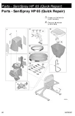
Parts - SaniSpray HP 65 (Quick Repair)

3A7653D

31

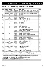
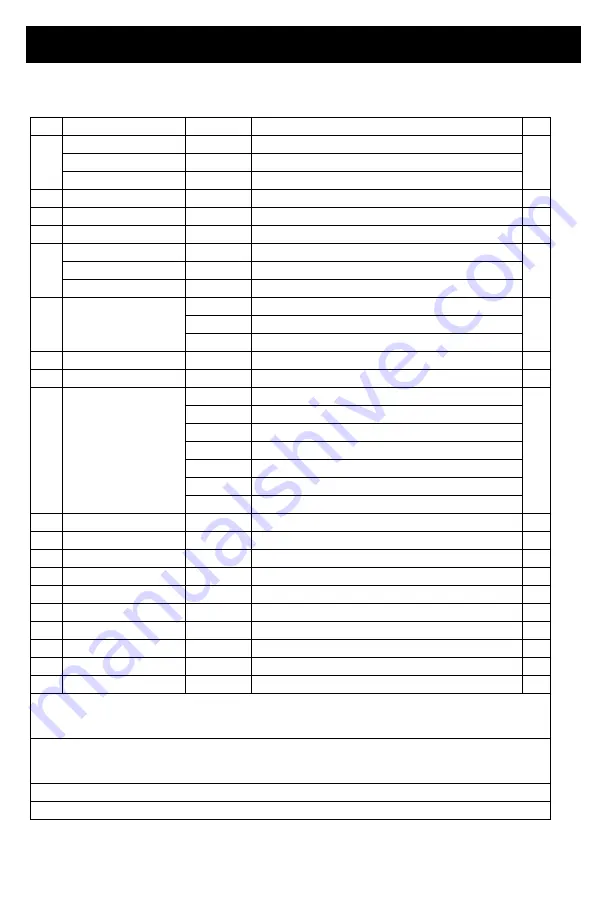
Parts List - SaniSpray HP 65 (Quick Repair)

Ref. Sprayer Model

Part

Description

Qty.

1

25R972, 25R962  25R921

KIT, motor, drive, HP65, 120V, 

includes 56

1

25R946

25T291

KIT, motor, drive, 230V, CEE, 

includes 56

25R948, 25R954 25T292

KIT, motor, drive, 230V, multi, 

includes 56

7

All

25R920

KIT, pump

1

8

All

25R922

KIT, enclosure

1

26

All

25R923

KIT, hopper

1

31†

25R792

25R874

GUN, SaniSpray, HP, NA 

1

25R946, 25R948 25T289

GUN, SaniSpray, HP, EU 

25R954, 25R962 25T290

GUN, SaniSpray, HP, AP 

32

All

LP617

TIP, LP617

1

LP619 †

TIP, LP619

LP621

TIP, LP621

36

All

112133

SCREEN, hopper

1

56

All

25T410

KIT, warning labels, cord

1

60

All

CARD, medical alert (not shown)

1

222385

English, Spanish, French

17F690

Dutch, German, Italian

17A134

English, Chinese, Korean

17R476

English, Spanish, Portuguese (Brazil)

26A997

English, Indonesian, Hindi

26A998

English, Chinese, Japanese

98

All

25T282

EXTENSION, 15 in. (not shown)

1

99*

All

25R872

TIPSEAL, 5-pack (not shown)

1

101

All

25C828

HOSE, 1/8 in. x 4-1/2 ft.

1

118

25R948, 25R954 195551

PLUG, retaining

1

144

25R962

244285

CORDSET, Japan (not shown)

1

146

25R954

17N232

CORDSET, India (not shown)

1

147

25R948, 25R954 242001

CORDSET, EU Schuko

1

149

25R954

242005

CORDSET, ANZ

1

157

25R948

287121

CORDSET, Italy, Denmark, Switzerland

1

158

25R948

17J242

CORDSET, UK (not shown)

1


Motor/Drive Kit 25R921 does not include cordset adapter for Japan. Cordset adapter 

must be ordered separate (see Ref. 144). Control Kit 25T292 does not include cordset 

adapter. Cordset adapter must be ordered separate (see Ref. 146-158).

Two extra TipSeals (polymer spray tip seals) are included with the sprayer. For 

disinfectant applications, use TipSeal (polymer spray tip seal) instead of the OneSeal 

(metal seal) that is included with the replacement spray tips.

† 

SaniSpray HP Gun includes LP619 Spray Tip.

Replacement safety labels, tags, and cards are available at no cost. 

Summary of Contents for SaniSpray HP 65

Page 1: ...usage of the equipment Save these instructions Important Medical Information Read the medical alert card provided with the sprayer It contains injection injury treatment information for a doctor Keep it with you when operating the equipment WARNING CHEMICAL HAZARD To prevent serious injury Follow all directions and requirements on disinfectant label It is a violation of Federal law to use an EPA a...

Page 2: ...g Your Spray and Adjusting Pressure 18 Clear Tip Clog 19 Cleanup 20 Clean the Gun 21 Storage 22 Quick Reference 23 Maintenance 24 Airless Hoses 24 Spray Tips 24 Pump Repair 24 Pump Removal 24 Pump Installation 25 Inlet Valve Removal 26 Recycling and Disposal 26 End of Product Life 26 Troubleshooting 27 Parts SaniSpray HP 65 Quick Repair 30 Parts SaniSpray HP 65 Extended Repair 32 Parts SaniSpray H...

Page 3: ...odels 110474 Certified to CAN CSA C22 2 No 68 Conforms to UL 1450 Maximum Working Pressure 1000 psi 6 9 MPa 69 bar VAC Model 120 USA 25R792 230 CEE 7 7 25R946 230 Europe Multi 25R948 240 AP Multi 25R954 100 JP TW 25R962 ...

Page 4: ...safety warnings in this manual NON ALCOHOL This type of disinfectant contains active ingredients such as aldehydes phenols quaternary ammonium compounds sodium hypochlorite bleach peroxyacetic acid hydrogen peroxide and hypochlorous acid Your sprayer is compatible with this type of material Before using your disinfectant sprayer read this manual for complete instructions on proper use and safety w...

Page 5: ...essure spray is able to inject toxins into the body and cause serious bodily injury that can result in amputation In the event that injection occurs get immediate surgical treatment Use only to spray surfaces Do not spray humans or animals Do not point spray tip at anyone or place any part of your body in front of tip For example do not try to stop leaks with any part of the body Always use the sp...

Page 6: ...flushing cleaning or servicing Do not spray pump assembly Do not smoke in the spray area or spray where sparks or flame is present Do not operate light switches engines or similar spark producing products in the spray area Keep area clean and free of disinfectant containers rags and other flammable materials Know the contents of the disinfectants being sprayed Read all Safety Data Sheet SDS and co...

Page 7: ...rs and other body parts Keep clear of moving parts Do not operate equipment with protective guards or covers removed Pressurized equipment can start without warning Before checking moving or servicing equipment follow the Pressure Relief Procedure and disconnect all power sources PERSONAL PROTECTIVE EQUIPMENT Wear appropriate protective equipment when in the work area to help prevent serious injur...

Page 8: ...When repair or replacement of the cord or plug is required do not connect the grounding wire to either power terminal The wire with insulation having an outer surface that is green with or without yellow stripes is the grounding wire Check with a qualified electrician or serviceman when the grounding instructions are not completely understood or when in doubt as to whether the product is properly ...

Page 9: ...n H Spray Tip J Spray Tip Guard K Trigger Lock L Hose Guard N ProXChange Pump behind Easy Access Door P Fluid Outlet Fitting Airless Hose con nection Q Airless Hose R Airless Whip Hose U Power Cord V Easy Access Door X Pump Removal Tool Z Inlet Valve Removal Tool Inlet Strainer inside hopper not shown Model Serial Tag bottom of unit not shown See Quick Reference page 23 for more information ...

Page 10: ...h alcohol active ingredients Follow local code Use only conductive metal pails Ground the metal pail by either placing it on a grounded surface or by attaching a ground wire Grounded surface method Place pail on a grounded surface such as concrete Do not place pail on a non conductive surface such as paper or cardboard which interrupts grounding continuity Ground wire method Connect a ground wire ...

Page 11: ...ting remove red storage plug from fitting if present Use wrenches to tighten securely 2 Assemble optional 1 8 Airless Whip Hose to end of 1 4 Airless Hose Use wrenches to tighten securely 3 Insert other end of Airless Whip Hose through Hose Guard at base of Spray Gun Connect to Spray Gun Use wrenches to tighten securely 4 Remove Spray Tip Guard assembly from Spray Gun ...

Page 12: ... sprayer is stopped to prevent the Spray Gun from being triggered accidentally 3 Turn Pressure Control Knob to the lowest setting This equipment stays pressurized until pressure is manually relieved To help prevent serious injury from pressurized fluid such as skin injection or splashing fluid follow the Pressure Relief Procedure whenever sprayer is stopped and before sprayer is cleaned or checked...

Page 13: ...essure 6 Engage the Trigger Lock 7 If you suspect the Spray Tip or hose is clogged or that pressure has not been fully relieved a VERY SLOWLY loosen the Spray Tip Guard retaining nut or the Airless Hose end coupling to relieve pressure gradually b Loosen the nut or coupling completely c Clear Airless Hose or Spray Tip obstruction Trigger Lock Always engage the Trigger Lock when sprayer is stopped ...

Page 14: ...e certain ON OFF Switch is OFF a Lift Drain Tube with retainer off the Hopper b While holding the Drain Tube retainer with the Drain Tube parallel to the top of a waste bucket twist retainer over the lip of the container Drain Tube should now be inside the waste bucket c Pour approximately two quarts of warm soapy water into the Hopper 3 Turn Prime Spray Valve horizontal to PRIME position 4 Plug p...

Page 15: ...OFF Switch to OFF position Fill Pump Refer to disinfectant label for manufacturer s directions on proper use If dilution is required properly dilute disinfectant prior to use 1 Addproperlyprepareddisinfectanttothe Hopper 2 Turn ON OFF Switch to ON position 3 Wait to seedisinfectantcomingout of the Drain Tube 4 Turn ON OFF Switch to OFF position NOTE Pump may prime faster if the ON OFF Switch is mo...

Page 16: ... 3 Release trigger Engage Trigger Lock 4 Inspect Airless Hose connections for leaks If leaks occur perform Pressure Relief Procedure page 12 then tighten all fittings and repeat Start Up If there are no leaks continue with the next step 5 Clip Drain Tube to Hopper NOTE When motor stops sprayer is pres surized If motor continues to run sprayer is not properly primed repeat Fill Pump and Fill Spray ...

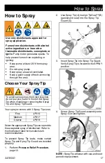
Page 17: ...rward in the SPRAY position 4 Screw Spray Tip Guard assembly onto Spray Gun and tighten NOTE Spray Tip will wear with use and need periodic replacement Use only disinfectants approved for spray application Fumes from disinfectants with alcohol active ingredients or from other flammable disinfectants can explode or ignite Pump motor generates sparks To help prevent fumes from exploding or igniting ...

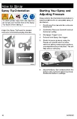
Page 18: ... sprayed 2 Confirm the Pressure Control Knob is at the lowest setting 3 Disengage Trigger Lock 4 Pull and hold Spray Gun trigger 5 Slowly increase pressure using the Pressure Control Knob Set to the minimum setting necessary to produce an acceptable spray of disinfect This will help reduce overspray 6 AdjusttheSprayGun sdistancefromthe surface and your hand speed to achieve the desired surface cov...

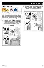
Page 19: ... a reversible Spray Tip that quickly and easily clears the particles without disassembling the Spray Gun 1 Release Trigger Engage Trigger Lock Rotate Spray Tip to UNCLOG position Disengage Trigger Lock Trigger Spray Gun in waste bucket to clear clog UNCLOG 2 Engage Trigger Lock Rotate Spray Tip back to SPRAY position Disengage Trigger Lock and continue spraying SPRAY ...

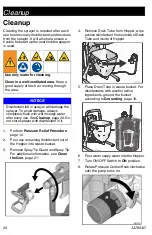
Page 20: ... from Hopper wipe excess disinfectant from outside of Drain Tube and inside of Hopper 5 Place Drain Tube in waste bucket For disinfectants with alcohol active ingredients ground the bucket according to Grounding page 10 6 Pour warm soapy water into the Hopper 7 Turn ON OFF Switch to ON position 8 RotatePressure ControlKnob clockwise until the pump turns on Use only water for cleaning Clean in a we...

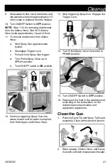
Page 21: ...r d Turn Prime Spray Valve up to SPRAY position e Turn ON OFF switch to ON position 12 Continue triggering Spray Gun into waste bucket until all water is emptied from the Hopper and Airless Hose 13 Stop triggering Spray Gun Engage the Trigger Lock 14 Turn Prime Spray Valve horizontal to PRIME position 15 Turn ON OFF Switch to OFF position 16 Dispose of the fluid in the waste bucket according to th...

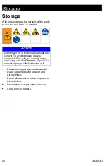
Page 22: ...er is drained out of sprayer and Airless Hose Do not allow water to freeze in sprayer or Airless Hose Do not store sprayer under pressure Store sprayer indoors Disinfectant left in sprayer will damage the sprayer To avoid damage always completely flush with warm soapy water after every use See Cleanup page 20 Do not store sprayer with disinfectant in it ...

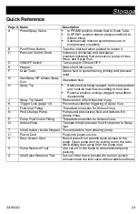
Page 23: ... hole size Reverse position unclogs plugged tips without disassembly J Spray Tip Guard Reduces risk of fluid injection injury K Trigger Lock page 13 Prevents accidental triggering of Spray Gun L Fluid Inlet Fitting Threaded connection for Airless Hose N ProXChange Pump Pumps and pressurizes fluid and delivers it to Airless Hose P Pump Fluid Outlet Fitting Threaded connection for Airless Hose Q Air...

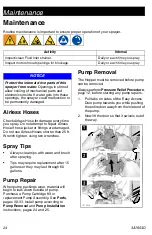
Page 24: ...ee Parts pages 30 33 Install pump according to Pump Removal and Pump Installation instructions pages 24 and 25 Pump Removal The Hopper must be removed before pump can be removed AlwaysperformPressureReliefProcedure page 12 before starting any pump repairs 1 3 ti27463a 2 1 Pull tabs on sides of the Easy Access Door pump towards you while pushing the entire door away from the inlet end of the pump 2...

Page 25: ... 1 Slide pump assembly onto the mounting pins 2 Move pump displacement rod up or down until cap is level with the opening in the yoke 3 Swing Easy Access Door pump door closed while pushing the entire door towards the inlet end of the pump NOTE Door must be fully closed and latched before sprayer will operate ...

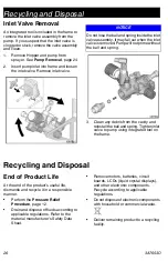
Page 26: ...ing and Disposal End of Product Life At the end of the product s useful life dismantle and recycle it in a responsible manner Perform the Pressure Relief Procedure page 12 Drain and dispose of fluids according to applicable regulations Refer to the material manufacturer s Safety Data Sheet Remove motors batteries circuit boards LCDs liquid crystal displays and other electronic components Recycle a...

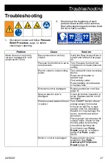
Page 27: ...ding power Test outlet with known working device Reset circuit breaker or replace fuse Find working outlet Reset building circuit breaker or replace fuse Extension cord is damaged Replace extension cord See page 10 Sprayer electric cord is damaged Check for broken insulation or wires Replace electric cord if damaged Pump is seized water is frozen in pump Turn ON OFF Switch off and unplug sprayer f...

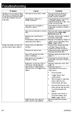
Page 28: ...arts pages 30 33 Pump is primed but can not achieve good spray pattern Spray Tip is in UNCLOG position Rotate arrow shaped handle on Spray Tip so it points forward to SPRAY position Pressure is set too low Increase pressure setting of Pressure Control Knob Spray Tip gasket and seal worn or missing Replace gasket and seal See page 17 Inlet strainer is clogged or Hopper is empty Clean debris off inl...

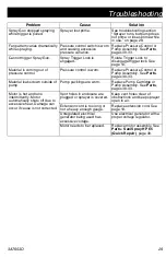
Page 29: ...lace Pressure Control or Pump Assembly See Parts pages 30 33 Material leaks down outside of pump Pump packings are worn Replace Pump Cartridge or Pump Assembly See Parts pages 30 33 Motor is hot and runs intermittently Motor automatically shuts off due to excessive heat Damage can occur if cause is not corrected Vent holes in enclosure are plugged or sprayer is covered Keep vent holes clear of obs...

Page 30: ...Parts SaniSpray HP 65 Quick Repair 30 3A7653D Parts SaniSpray HP 65 Quick Repair Torque to 110 120 in lb 12 5 13 6 N m Torque to 30 36 in lb 3 4 4 0 N m 1 2 ...

Page 31: ... Hindi 26A998 English Chinese Japanese 98 All 25T282 EXTENSION 15 in not shown 1 99 All 25R872 TIPSEAL 5 pack not shown 1 101 All 25C828 HOSE 1 8 in x 4 1 2 ft 1 118 25R948 25R954 195551 PLUG retaining 1 144 25R962 244285 CORDSET Japan not shown 1 146 25R954 17N232 CORDSET India not shown 1 147 25R948 25R954 242001 CORDSET EU Schuko 1 149 25R954 242005 CORDSET ANZ 1 157 25R948 287121 CORDSET Italy...

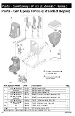
Page 32: ...2 25R962 25T416 BOARD control 100 120V includes 15a 1 25R946 25R948 25R954 25T417 BOARD control 220 240V includes 15a 15a 25R792 25R962 119276 FUSE 12 5A slow blow 100 120V 1 25R946 25R948 25R954 129882 FUSE 6 3A slow blow 220 240V 39 All 17K336 TUBE drain assembly 1 56 All 25T410 KIT warning labels cord 1 Replacement safety labels tags and cards are available at no cost Torque to 110 120 in lb 12...

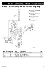
Page 33: ...t Description Qty 6 All 25T403 KIT inlet valve assembly 1 8 All 25T415 KIT prime valve 1 25 All 25T418 KIT pump cartridge 1 28 All 25T402 KIT control pressure 1 Torque to 140 160 in lb 16 18 N m Torque to 270 330 in lb 30 37 N m Torque to 30 35 ft lb 40 48 N m Torque to 220 250 in lb 25 28 N m 1 2 3 4 ...

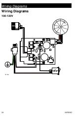
Page 34: ...Wiring Diagrams 34 3A7653D Wiring Diagrams 100 120V ti27233a M ...

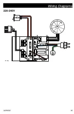
Page 35: ...Wiring Diagrams 3A7653D 35 220 240V ti27485a M ...

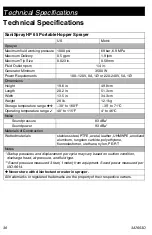
Page 36: ...erature range 30 to 160 F 35 to 71 C Operating temperature range 40 to 115 F 4 to 46 C Noise Sound pressure 83 dBa Sound power 93 dBa Materials of Construction Wetted materials stainless steel PTFE acetal leather UHMWPE anodized aluminum tungsten carbide polyethylene fluoroelastomer urethane nylon PE RT Notes Startup pressures and displacement per cycle may vary based on suction condition discharg...

Page 37: ...California Proposition 65 3A7653D 37 California Proposition 65 CALIFORNIA RESIDENTS WARNING Cancer and reproductive harm www P65warnings ca gov ...

Page 38: ... WITH ACCESSORIES EQUIPMENT MATERIALS OR COMPONENTS SOLD BUT NOT MANUFACTURED BY GRACO These items sold but not manufactured by Graco such as electric motors switches hose etc are subject to the warranty if any of their manufacturer Graco will provide purchaser with reasonable assistance in making any claim for breach of these warranties IN NO EVENT WILL GRACO BE LIABLE FOR INDIRECT INCIDENTAL SPE...

Page 39: ...Information For the latest information about Graco products visit www graco com For patent information see www graco com patents TO PLACE AN ORDER contact your Graco distributor or call 1 800 690 2894 to identify the nearest distributor ...

Page 40: ... changes at any time without notice Original instructions This manual contains English MM 3A7653 Graco Headquarters Minneapolis International Offices Belgium China Japan Korea GRACO INC AND SUBSIDIARIES P O BOX 1441 MINNEAPOLIS MN 55440 1441 USA Copyright 2020 Graco Inc All Graco manufacturing locations are registered to ISO 9001 www graco com Revision D July 2020 ...

Reviews: