Repair
20
311512A
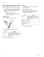
Fluid Temperature Sensor (FTS)
Check FTS operation by connecting directly to Reactor.
FTS Cable Test
1.
Disconnect FTS cable (SS) at Reactor.
2.
Test with ohmmeter between pins of cable
connector.
3.
If cable fails test, retest at FTS.
FTS Test
1.
Turn Main Disconnect Switch OFF. Disconnect
power supply cord.
2.
Relieve pressure; see page 7.
3.
Remove tape and protective covering from FTS.
Disconnect hose cable. Test with ohmmeter
between pins of cable connector.
4.
If FTS fails test, replace FTS.
An alternating hose controller display of SbEr and
H0.00 indicates a loss of signal from the FTS. Two
conditions must be satisfied for proper FTS
operation:
•
The sensor must be functional
•
The signal must travel uninterrupted from the
sensor to the control unit
Pins
Result
1 to 2
Approximately 35 ohms per 50 ft
(15.2 m) of hose, plus approximately
10 ohms for FTS
1 to 3
Infinity
SS
ti8444a
Pins
Result
1 to 2
Approximately 35 ohms per 50 ft
(15.2 m) of hose, plus approximately
10 ohms for FTS
1 to 3
Infinity
3 to FTS ground
screw
0 ohms
1 to FTS com-
ponent A fitting
(ISO)
Infinity
Summary of Contents for Reactor A-20
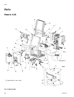
Page 31: ...Parts 311512A 31 ...
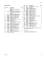
Page 35: ...Parts 311512A 35 ...
Page 38: ...Reactor A 20 Wiring Schematic 38 311512A Reactor A 20 Wiring Schematic ...
Page 39: ...Reactor A 20 Wiring Schematic 311512A 39 ...
Page 40: ...Reactor A 20 Wiring Schematic 40 311512A ...
Page 41: ...Reactor A 20 Wiring Schematic 311512A 41 ...
Page 42: ...Reactor A 20 Wiring Schematic 42 311512A ...
Page 43: ...Wiring Diagrams 311512A 43 Wiring Diagrams Heater Circuit ...
Page 44: ...Wiring Diagrams 44 311512A Pump Circuit ...
Page 45: ...Wiring Diagrams 311512A 45 Hose Circuit ...
Page 46: ...Wiring Diagrams 46 311512A ...


