Repair
14
311512A
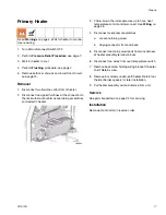
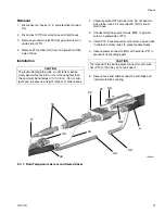
Pump Installation
1.
Ensure locknut (431) is screwed on pump with flat
side up. Grease pump mounting threads in plate
(412) with lithium grease. Screw pump into pump
mounting plate (401) until top of pump thread is
above mounting plate 1/2 to 1 1/2 threads above
flush.
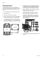
2.
Align pump rod hole with link hole. Push retaining
pin (436) in. Pull retaining wire down to cover pin
ends.
3.
Reconnect fluid inlet (Q) and outlet (M).
4.
Tighten locknut (431) by hitting firmly with a
non-sparking hammer.
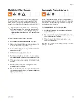
5.
For Iso A pump only: reconnect two tubing lines (N)
from ISO Pump Lube reservoir. Flush and refill res-
ervoir with TSL 206995.
6.
Refill Resin B pump wet cup with TSL 206995.
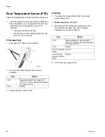
7.
Reconnect fan wires if they were disconnected.
8.
Reinstall air motor cover and tighten two screws (E).
ti8456a
431
412
452
454,
455
M
Q
ti8487a
N
ti8455a
E
Summary of Contents for Reactor A-20
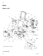
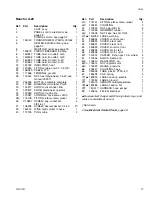
Page 31: ...Parts 311512A 31 ...
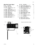
Page 35: ...Parts 311512A 35 ...
Page 38: ...Reactor A 20 Wiring Schematic 38 311512A Reactor A 20 Wiring Schematic ...
Page 39: ...Reactor A 20 Wiring Schematic 311512A 39 ...
Page 40: ...Reactor A 20 Wiring Schematic 40 311512A ...
Page 41: ...Reactor A 20 Wiring Schematic 311512A 41 ...
Page 42: ...Reactor A 20 Wiring Schematic 42 311512A ...
Page 43: ...Wiring Diagrams 311512A 43 Wiring Diagrams Heater Circuit ...
Page 44: ...Wiring Diagrams 44 311512A Pump Circuit ...
Page 45: ...Wiring Diagrams 311512A 45 Hose Circuit ...
Page 46: ...Wiring Diagrams 46 311512A ...


