Repair
311512A
17
Primary Heater
1.
Turn Main disconnect Switch OFF.
2.
Perform Pressure Relief Procedure; see page 7.
3.
Wait for heater to cool.
4.
Perform Flushing procedure; see page 7.
5.
Remove both rear shrouds and lower front shroud;
see page 12.
Removal
1.
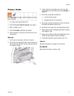
Disconnect two fluid lines at bottom of heater.
2.
Disconnect two upper fluid lines at the connection to
the recirculation manifold. Leave tubing assemblies
connected to heater.
3.
Follow brown thermocouple wire up to hose heat
temperature control and disconnect. See Wiring on
page 35.
4.
Disconnect over pressure switches.
a.
Loosen retaining screw.
b.
Unplug connector front and back.
5.
Disconnect two main power leads from wire harness
at heater assembly terminal blocks.
6.
Disconnect two wires from over temperature switch.
7.
Remove back screw holding wiring bracket to heater
shelf. Retain screw.
8.
Remove four screws underneath heater. Retain four
thermal barrier spacers for later installation.
9.
Pull heater assembly out and remove from unit.
Service
See parts breakdown on page 34 for servicing.
Installation
Reconnect and install in reverse order.
Read Warnings on page 4. Wait for heater to cool be-
fore repairing.
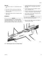
ti8484a
Summary of Contents for Reactor A-20
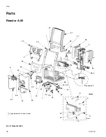
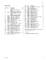
Page 31: ...Parts 311512A 31 ...
Page 35: ...Parts 311512A 35 ...
Page 38: ...Reactor A 20 Wiring Schematic 38 311512A Reactor A 20 Wiring Schematic ...
Page 39: ...Reactor A 20 Wiring Schematic 311512A 39 ...
Page 40: ...Reactor A 20 Wiring Schematic 40 311512A ...
Page 41: ...Reactor A 20 Wiring Schematic 311512A 41 ...
Page 42: ...Reactor A 20 Wiring Schematic 42 311512A ...
Page 43: ...Wiring Diagrams 311512A 43 Wiring Diagrams Heater Circuit ...
Page 44: ...Wiring Diagrams 44 311512A Pump Circuit ...
Page 45: ...Wiring Diagrams 311512A 45 Hose Circuit ...
Page 46: ...Wiring Diagrams 46 311512A ...


