background image

Repair and Maintenance 

6

3A5573C

Repair and Maintenance

Pressure Relief Procedure

1.

Turn off power supply to the pump.
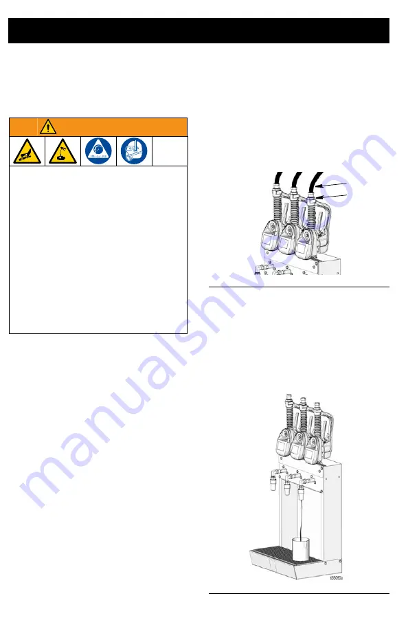
2.

Place a container under the drain valve 
on the oil bar (F

IG

. 18). Open the nozzle.

3.

Pull trigger to dispense as much of the 
fluid as possible to relieve pressure.

4.

Leave the nozzle open until you are 
ready to pressurize the system.

Oil Bar Disassembly

1.

Relieve pressure. See the Pressure 
Relief Procedure.

2.

Disconnect fluid distribution lines (c) 
from fitting (3) (see F

IG

. 17).

3.

Pull trigger to dispense as much of the 
fluid remaining in the line as possible 
(F

IG

. 18).

NOTE:

 A collection container should 

already be in place and the nozzle 
should be open after performing 
Pressure Relief Procedure (Step 1).

WARNING

PRESSURIZED FLUID HAZARD

This equipment stays pressurized until 
pressure is manually relieved. To help pre-
vent serious injury from pressurized fluid, 
such as skin injection, splashing fluid and 
moving parts, follow the Pressure Relief 
Procedure when you stop dispensing and 
before cleaning, checking, or servicing the 
equipment.

PERSONAL PROTECTIVE EQUIPMENT

Wear appropriate protective equipment 
when in the work area to help prevent 
serious injury, including eye injury, hearing 
loss, inhalation of toxic fumes, and burns.

F

IG

. 17

F

IG

. 18

3

c

Summary of Contents for Pulse 25D121

Page 1: ...spense valves for installation in the oil bar NOTE One Model 25D130 is required for each model 24N415 metered dispense valve Maximum Working Pressure 1500 psi 103 bar 10 MPa Model No 25D121 Oil Dispen...

Page 2: ...ation An o ring is required and installed on fitting 3 3 Install fitting 1 in the outlet as shown in FIG 3 Tighten fitting with a wrench 4 Install Graco identification label 7 over the existing GRACO...

Page 3: ...ecting fasteners consider the weight of the oil bar metered dispense valves plumbing fixtures and dispensed oil in the container placed on the shelf See Technical Specifications page 10 3 Attach the m...

Page 4: ...determine the correct installation position 2 If installed when assembling the Oil Bar remove screws 27 and remove access panel 25 3 Position manifold 2 inside oil bar orienting opening a on the fron...

Page 5: ...PTFE tape or thread sealant as shown in FIG 13 7 Install the end of the nipple adapter 10 that was wrapped in the PTFE tape or treated with thread sealant into the manifold 2 through the hole b in the...

Page 6: ...he fluid remaining in the line as possible FIG 18 NOTE A collection container should already be in place and the nozzle should be open after performing Pressure Relief Procedure Step 1 WARNING PRESSUR...

Page 7: ...removed form the manifold as a single assembly FIG 21 7 Remove screws 5 and washers 4 from manifold 2 Lift manifold 2 straight up and out of the oil bar housing FIG 22 8 To protect the metered dispen...

Page 8: ...ITTING 3 4 ORB UNF X 3 8 NPSM 1 2 131245 MANIFOLD dispenser 1 3 131246 FITTING 1 1 16 ORB UNF X 1 2 NPSM 1 4 100016 WASHER lock 2 5 108296 SCREW hex 2 6 121079 SWIVEL elbow ORB X NPSM 1 7 130195 LABEL...

Page 9: ...Qty 21 181316 WRAPPER dispenser 1 22 16D537 PAN drain coating 1 23 181319 STRAINER pan 1 24 131242 PLATE mount 1 25 131243 PLATE cover panel 1 26 104663 PLUG pipe 1 27 108296 SCREW hex 18 28 100016 W...

Page 10: ...ns 10 3A5573C Technical Specifications Oil Bar US Metric Maximum Working Pressure 1500 psi 103 bar 10 MPa Wetted Materials Carbon steel aluminum Buna n rubber Weight Model 25D121 30 lbs 13 61 kg Model...

Page 11: ...NOTES 3A5573C 11 NOTES...

Page 12: ...n material or workmanship repairs will be made at a reasonable charge which charges may include the costs of parts labor and transportation THIS WARRANTY IS EXCLUSIVE AND IS IN LIEU OF ANY OTHER WARRA...

Reviews: