background image

308783

Rev. C

Supersedes B

First choice when

quality counts.

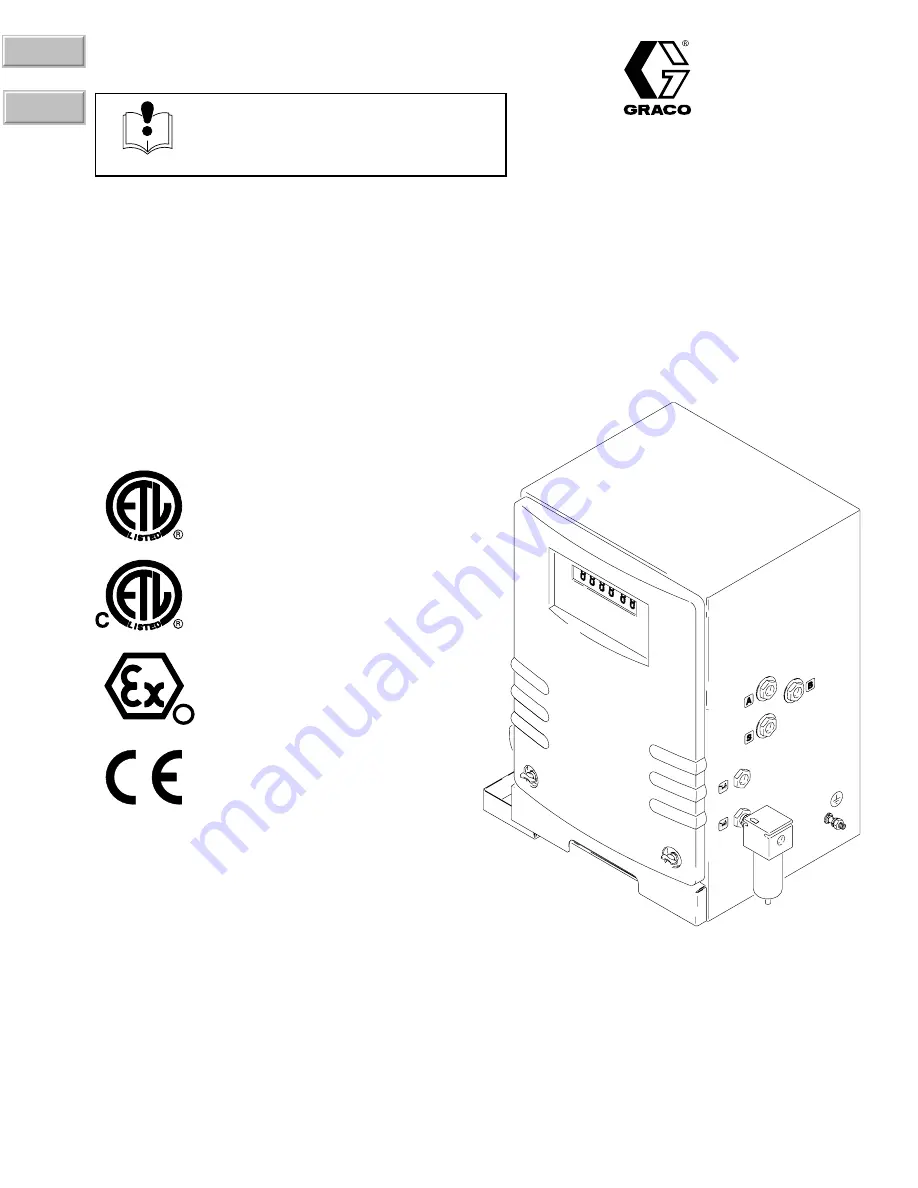
Certified  to CAN/CSA
22.2 No. E79–11–95

Conforms to ANSI/UL
standard 2279

Recognized Component

EExia II A T4

98D.123384

Intrinsically Safe for Hazardous Locations
Class 

I

; Division 1; Group D*

*

If an external power supply is connected to the control, the control
is no longer intrinsically safe and the control, as well as the power
supply, must not be operated in hazardous locations. 

If a printer is connected to the control, Printer Barrier Kit 240652
must be installed to maintain intrinsic safety. If the printer is
installed without the Printer Barrier Kit, the control is no longer
intrinsically safe and the control and printer must not be installed
or operated in hazardous locations.

D

7486A

INSTRUCTIONS-PARTS LIST

INSTRUCTIONS

This manual contains important
warnings and information.
READ AND KEEP FOR REFERENCE.

ProMix

 Control Assembly 

For proportional mixing of plural component coatings

3000 psi (21 MPa, 207 bar) Maximum Working Fluid Pressure
4000 psi (28 MPa, 276 bar) Maximum Fluid Working Pressure


with Part No. 239954 High Pressure Spring Kit

3000 psi (21 MPa, 207 bar) Maximum Solvent Supply Pressure
100 psi (0.7 MPa, 7 bar) Maximum Working Air Pressure

Part No. 239735

GRACO INC.

P.O. BOX 1441

MINNEAPOLIS, MN

55440–1441

COPYRIGHT 1997, GRACO INC.

Graco Inc. is registered to I.S. EN ISO 9001

Parts

Contents

Summary of Contents for ProMix 239735

Page 1: ...ed without the Printer Barrier Kit the control is no longer intrinsically safe and the control and printer must not be installed or operated in hazardous locations D 7486A INSTRUCTIONS PARTS LIST INSTRUCTIONS This manual contains important warnings and information READ AND KEEP FOR REFERENCE ProMix Control Assembly For proportional mixing of plural component coatings 3000 psi 21 MPa 207 bar Maximu...

Page 2: ...d 15 Adjusting Setup Values 16 Pressure Relief Procedure 17 Startup 18 Reporting 21 Shutdown 21 Purging 22 Purging the ProMix of Mixed Material 22 Purging the Fluid Supply 23 Ratio Check 25 Alarm Troubleshooting 28 To Clear the Alarm and Restart the System 28 Off Ratio Alarm 28 Dose Time of Component A or B Exceeded 29 Overdose A or Overdose B 29 Idle Time Exceeded 30 Pot Life Exceeded 30 Service ...

Page 3: ...d the equipment and the object being sprayed See Ground the System on page 13 The ProMix control is intrinsically safe when used without any external electrical components connected to it If an external power supply or printer is connected to the control the control is no longer intrinsically safe and the control as well as the power supply and printer must not be oper ated in hazardous locations ...

Page 4: ...i 21 MPa 207 bar maximum working fluid pressure The fluid supply for solvent purging must not exceed this maximum working pres sure Route the hoses away from the traffic areas sharp edges moving parts and hot surfaces Do not expose Graco hoses to temperatures above 180 F 82 C or below 40 F 40 C Use only Graco approved hoses Do not remove hose spring guards which help protect the hose from rupture ...

Page 5: ... B fluid line connection Solvent fluid line connection Ground wire connection Air line connection Gun air outlet Air signal outlet Alarm air outlet External power connector Printer cable connector Operator station connector Operator Station The following icons are on the front of the operator station They indicate the three operation modes mix standby and purge and the report function See page 14 ...

Page 6: ...y the pot life time remaining in minutes Note Pot life is the approximate length of time mixed fluid can remain in the system and stay at its normal viscosity The time length is entered during setup FLOW RATE Press to display the cur rent flow rate the system is producing in cc per minute Setup Mode Icons Read page 15 for information on the Reference Card and how to use it to select setup function...

Page 7: ...ME Press to adjust the purge time in seconds The default purge time is 62 seconds Shots of air and solvent alternate during the purge time Level 3 Icons OPEN COMPONENT A VALVE Hold down the key to open the component A valve The valve closes when the key is released Used for manual purging and color change OPEN COMPONENT B VALVE Hold down the key to open the component B valve The valve closes when ...

Page 8: ...nent B Line C ProMix Control D LED Display E Component A Supply F Component B Supply G Solvent Supply H Air Regulator I Fluid Filter 100 mesh minimum J Shut off Valve K Gun Air Line L Operator Station Cable M Gun Fluid Line N Main Air Line O Spray Gun S Solvent Line 51 Air Filter 63dKeypad 67 Mix Manifold 77 Operator Station ...

Page 9: ... operated in hazardous locations as defined in article 500 of the National Electrical Code USA or your local electrical code The Typical Installation shown in Fig 1 is only a guide line for selecting and installing system components and accessories and is not an actual system design Follow the installation schematic in the system binder provided by Graco or contact your Graco representa tive for a...

Page 10: ...ns inches mm A B C D E F 14 6 370 8 24 609 6 16 406 4 16 406 4 10 254 4 5 114 3 Fig 2 7488A 4 Screw the air filter 51 into the purge air inlet See Fig 3 5 Install a shut off valve J 1 into the air filter 51 to shut off the air to the mix manifold 6 Install a shut off valve J 2 into the control air inlet to shut off the air to the control 7 Connect two separate air lines to the two control air inle...

Page 11: ... 21 MPa 207 bar maximum working fluid pressure The fluid supply for solvent purging must not exceed this maximum working pressure 8 Connect the fluid supply lines to the ProMix control connectors See Fig 1 and 3 a Connect the component A resin line from the fluid supply to control connector A b Connect the component B catalyst line from the fluid supply to control connector B c Connect the solvent...

Page 12: ...n used without any external electri cal components connected to it If an external power supply or printer is connected to the control the control is no longer intrinsically safe and the control as well as the power supply and printer must not be operated in hazardous locations as defined in article 500 of the National Electrical Code USA or your local electrical code 11 If using a printer plug the...

Page 13: ...tainer according to your local code e Ground the object being sprayed according to your local code f Ground the solvent pails according to your local code Use only metal pails which are conductive placed on a grounded surface Do not place the pail on a nonconductive surface such as paper or cardboard which interrupts the grounding continuity g Maintain grounding continuity when purging or relievin...

Page 14: ...time to turn the switch to clear an alarm see Clearing Alarms below Clearing Alarms All alarms except the Pot Life Alarm can be cleared by moving the operator switch from mix to standby to purge to standby See page 28 for information on alarms Turn to mix to resume operation after clearing the alarm Report Button If a printer is connected to the control press the report button to generate a report...

Page 15: ...der that icon will be green and the last known target ratio will be displayed At startup that would be 1 0 1 Fig 10 Target Ratio Setup Level Icon Keypad Reference Card The Setup Mode icons which represent setup options are on the Reference Card provided See Fig 11 The meaning of each setup icon is described in Setup Mode Icons on page 6 The icons are lined up horizontally according to the setup le...

Page 16: ...so the last known hour will be displayed Hour Setup Level 6 Press the purge time icon This is the key under the icon on the keypad The light under the icon will turn green to indicate that function has been activated and the last known purge time setting will display NOTE The purge time displays in seconds and up to three digits can be entered The default purge time is 62 seconds Purge Time Setup ...

Page 17: ...andby 2 Shut off the control purge air J 1 J 1 7511A Air Shutoff Valve 3 Shut off the air at the spray gun 4 Relieve fluid and air pressure at the component and solvent feed pumps or pressure pots as explained in their separate instruction manuals 5 Set the operator switch to mix 6 Hold a metal part of the spray gun firmly to the side of a grounded metal pail and trigger the gun to relieve fluid p...

Page 18: ...knobs are set as follows T Fluid Shut off Knobs fully open U Dispense Valve Knobs three clicks open from fully closed setting V Purge Valve Knobs two turns open from fully closed setting W Ratio Check Valve Knobs fully closed 7384B U V T Reference T W 4 Turn the control air supply on J 1 J 2 A diagnostic test will run and the last known Target Ratio will display on the LED panel This will be a 1 0...

Page 19: ...due to alarms while priming the sys tem NOTE If the flow meters overrun because of air in the system operation will stop See Alarm Troubleshoot ing on page 28 a Touch the token on the back of the reference card to the setup contacts Z Number 1 appears on the display indicating the control is at level 1 setup Z Setup Level b Refer to the reference card and press the return key on the keypad twice t...

Page 20: ...el 1 setup X b Adjust the solvent fluid supply pressure X Use the lowest pressure possible to avoid splashing c Hold down the solvent valve key to open the solvent valve d Trigger the gun into a grounded waste con tainer until solvent flows from the nozzle e Release the solvent valve key to close the valve f Touch the token to the setup contacts to exit setup mode 14 Prime the lines with mixed mat...

Page 21: ...o standby and press the report button to generate a report NOTE The system must be in standby mode to run a report 7475A The control will reset the component A and B totalizers andl send the following information to the printer Start Date and Time End Date and Time Consumption A Consumption B Desired Ratio Ratio Tolerance Maximum Ratio Deviation Shutdown WARNING INJECTION HAZARD To reduce the risk...

Page 22: ... the equipment wetted parts and with the fluid being sprayed 2 Make sure the operator switch is set at standby 7475A WARNING FIRE EXPLOSION AND ELECTRIC SHOCK HAZARD To reduce the risk of fire explosion or electric shock the air to the gun must be shut off on a Graco PRO electrostatic spray gun to ensure the electrostatic power is not on when purging Air Shutoff Valve 3 Shut off the air at the spr...

Page 23: ...cing if production will not resume right away WARNING INJECTION HAZARD To reduce the risk of a serious injury follow the Pressure Relief Procedure on page 17 whenever you are instructed to relieve the pressure 1 Make sure the solvent is compatible with the equipment wetted parts and with the fluid being sprayed 2 Make sure the operator switch is set at standby 7475A WARNING FIRE EXPLOSION AND ELEC...

Page 24: ...grounded waste container until the component A fluid lines are clean ÄÄÄ ÄÄÄ 12 Release the component A valve key to close the valve 13 Hold down the component B valve key to open the component B valve Trigger the gun into a grounded waste container until the component B fluid lines are clean 14 Release the component B valve key to close the valve 15 If changing colors materials change the ratio a...

Page 25: ...rized If manual force cannot turn the valve stems the system pressure must be relieved and the valve properly disassembled and cleaned to remove the resistance Reference T W KEY T Fluid Shut off Knobs W Ratio Check Valve Knobs T 7384B 1 Make sure the operator switch is set at standby 7475A 2 Turn off all the spray or dispense devices con nected to the ProMix 3 Close both fluid shut off valves T an...

Page 26: ...ess the flow meter A key The amount of fluid dispensed will display in cubic centimeters cc Flow Meter Volume Setup Level 10 Compare the amount on the display to the amount in the component A beaker For maximum accu racy use a gravimetric mass method to deter mine the actual dispensed volumes Flow Meter Volume Setup Level Beaker A 7481A 11 If the amounts are different press the arrow keys no up or...

Page 27: ...f to one full turn Purge until clean solvent flows from the check valve then close the valve Reference T A W A T B 7384B W B g Release the ratio valve purge key to close the solvent valve 16 Make sure both component A and B ratio check valves W A W B are closed and both fluid shut off valves T A T B are fully open 17 Touch the token to the setup contacts to save the new value entered during the ra...

Page 28: ...id supply system Slow actuation of the component A or B valves Checking the Flow Rate If the alarm occurs while starting up the system after purging the flow rate was probably too high Restrict the gun needle travel to slow down the initial fluid delivery rate until the fluid hoses are loaded with material Checking for Unbalanced Pressures If the alarm occurred after you have been spraying for som...

Page 29: ...spense valve open indefinitely because the control will never see the target value being reached This condition could cause the operator to spray pure component A or B onto a part To prevent this from happening the control will only allow the component A or B valve to remain open for the duration of the dose time The dose time begins when the flow switch detects air flow to the gun The alarm will ...

Page 30: ...ix for too long when no fluid is being dispensed If the gun air is being used when the alarm occurs the air flow switch and a flow meter have failed If spraying airless or air is supplied to gun by other means than the ProMix unit and the alarm occurs the flow meter has failed Checking for an Air Flow Switch Failure If the operator switch was turned to mix for too long when no fluid was being disp...

Page 31: ... dispensed off ratio as it may not cure properly NOTE If the ratio is set to 0 6 1 to 20 1 the ratio will remain at its setting when powered off and on If the ratio is set to 0 5 1 or less and the system is powered off and on the ratio will reset to the default of 1 1 All other settings will also reset to their default values Instruction Manuals Additional instruction manuals are included with the...

Page 32: ...cal 3 Put on the grounding strap provided 4 Remove the control front cover 2 See Fig 12 5 Loosen the two screws 21 from the control panel 63 to allow the panel to drop forward 6 Disconnect the wire harnesses 94 95 from the two circuit board connectors AC 7 Unscrew the four screws 63c and remove the circuit board cover AA 8 Disconnect the ribbon cable AB Replacing the Keypad 9 Pull the keypad 63d o...

Page 33: ... 13 7 Unscrew the two allen screws AD and remove the solenoid 75a 8 Make sure the gasket is in place on the new solenoid and secure it to the solenoid manifold 75h with the screws AD 9 Connect the wire harness 95 to the solenoid electrical connector 10 Close the panel 63 be sure not to crimp or pinch the wires Secure the panel with the screws 21 11 Install the front cover 2 See Fig 12 7494A Fig 13...

Page 34: ...17 45 7 Disconnect the wire harness 94 from the meter electronic sensor 8 Remove the screws 68 from the back of the meter 20 and remove the meter 9 Repair the meter as instructed in the separate meter manual 10 Secure the meter 20 to the control cabinet with the screws 68 11 Connect the wire harness 94 to the meter elec tronic sensor 12 Connect the meter fluid lines 16 46 and or 17 45 13 Push in t...

Page 35: ... air purge line P See Fig 17 12 Disconnect the air lines c k 13 Unscrew the four screws 68 from the bottom of the plate 4 and slide out the mix manifold 67 See Fig 16 14 Repair the manifold as instructed in the separate mix manifold manual 15 Place the mix manifold 67 on the plate 4 and secure it with the screws 68 16 Connect the air lines and fluid lines Refer to Fig 17 Continued on the next page...

Page 36: ... sepa rate the power supply housings AI AJ 8 Disconnect the 3 wire connector AK from the circuit board 74c 9 Carefully pull the alternator 74g out of the hous ing AI 10 Use an ohmmeter to test the turbine alternator coil Measure the resistance between the two outer terminals of the 3 wire connector AK The resist ance should be 3 to 5 ohms If the reading varies from this value replace the alternato...

Page 37: ...ted to the control alarm air outlet 92 decibels at 100 ft 30 5 239811 Reference Card with Token For setup access and reference to available options 223688 Turbine Alternator Repair Kit Includes two bearings and a fan Bearings should be replaced after 2000 hours of operation To maintain intrinsic safety only use this Graco kit to replace bearings and follow the service instructions provided with th...

Page 38: ... 21 22 2 23 51 58 61 73 23 51 30 25 26 59 60 27 27 29 28 23 24 48 54 4 21 22 10 18 18 10 20 19 9 12 11 12 13 14 11 3 62 67 73 88 89 90 68 49 73 1 52 53 94 See page 39 for Detail drawings See page 41 for air and fluid line locations 50 68 Detail E Detail D 73 73 8 9 15 5 110 14 13 ...

Page 39: ... 33 7499A 74h 74a 74c 74j 74g 74f 74d 74b 74e 74k 7514A 36 7493A 95 63a 63d 63b 63c 63 Detail E Control Panel 7509A Ref 67 81a 87 86 85 84 81 81b Detail D Static Mixer NOTE Exploded assembly orientation reversed to clearly see parts 7630A 75a 75k 75h 75b 75j 89 71 95 75 Ref 74b NOTE Refer also to Fig 16 page 35 ...

Page 40: ... 32 192652 SWITCH air flow 1 33 114128 ELBOW swivel 1 2 OD tube x 1 4 npt 1 34 114130 TEE swivel 1 2 OD tube x 1 4 npt 1 Ref No Part No Description Qty 35 114156 REDUCER 1 4 x 1 2 OD push in tube 1 36 114157 ELBOW union 1 2 OD push in tube 1 37 114163 WASHER shoulder nylon 0 174 4 38 114165 SCREW machine M4 x 16 2 39 114164 WASHER flat nylon 3 8 4 40 105689 NUT machine hex M4 x 0 7 4 41 113284 BUL...

Page 41: ...1 4 OD 1 77 114173 OPERATOR STATION not shown 1 78 112190 GROUNDING STRAP wrist not shown 1 79 114221 TUBE nylon clear 1 4 OD 80 192935 TUBE nylon white 1 2 OD 81 239862 MIXER static Includes items 81a 81b 1 81a 513697 ADAPTER 3 8 OD tube x 1 4 BSPT 1 81b 513817 BULKHEAD 3 8 x 1 4 npt 1 84 192590 BRACKET static mixer 1 85 112789 WASHER plain 1 4 1 86 100016 WASHER lock 1 4 1 Ref No Part No Descrip...

Page 42: ...42 308783 Dimensions A F D E C B 7488A Dimensions inches mm A B C D E F 14 6 370 8 24 609 6 16 406 4 16 406 4 10 254 4 5 114 3 ...

Page 43: ...epoxy or polyurethane paints Viscosity range of fluid 20 to 5000 cps Fluid filtration 100 mesh minimum Fluid flow rate range 3 4 to 68 oz min 100 to 2000 cc min Operating temperature range 41 to 104 F 5 to 40 C External Power Supply Requirements 12 24 Vdc 0 3 amp Weight 115 lbs 52 kg Wetted parts 303 304 SST 17 4 SST Tungsten carbide with nickel binder Chemraz Teflon CV75 NOTE See the individual c...

Page 44: ...t forth above The buyer agrees that no other remedy including but not limited to incidental or consequential damages for lost profits lost sales injury to person or property or any other incidental or consequential loss shall be available Any action for breach of warranty must be brought within two 2 years of the date of sale GRACO MAKES NO WARRANTY AND DISCLAIMS ALL IMPLIED WARRANTIES OF MERCHANT...

Reviews: