


313937A
Instructions
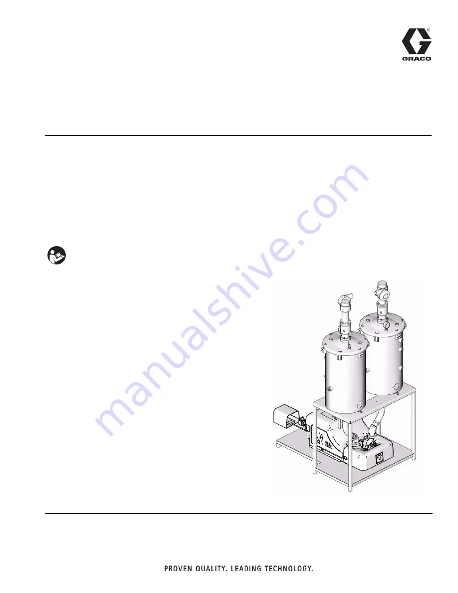
Pneumatic PR70
For accurate metering, mixing, and dispensing of two-component materials.
SN8050
3000 psi (21 MPa, 207 bar) Maximum Working Pressure
100 psi (0.7 MPa, 7 bar) Maximum Air Inlet Pressure
Important Safety Instructions
Read all warnings and instructions in all sup-
plied manuals. Save these instructions.
Dispense Valve not shown
Summary of Contents for Pneumatic PR70
Page 32: ...Dimensions 32 313937A ...


