background image

313877J

EN

Setup - Operation - Parts
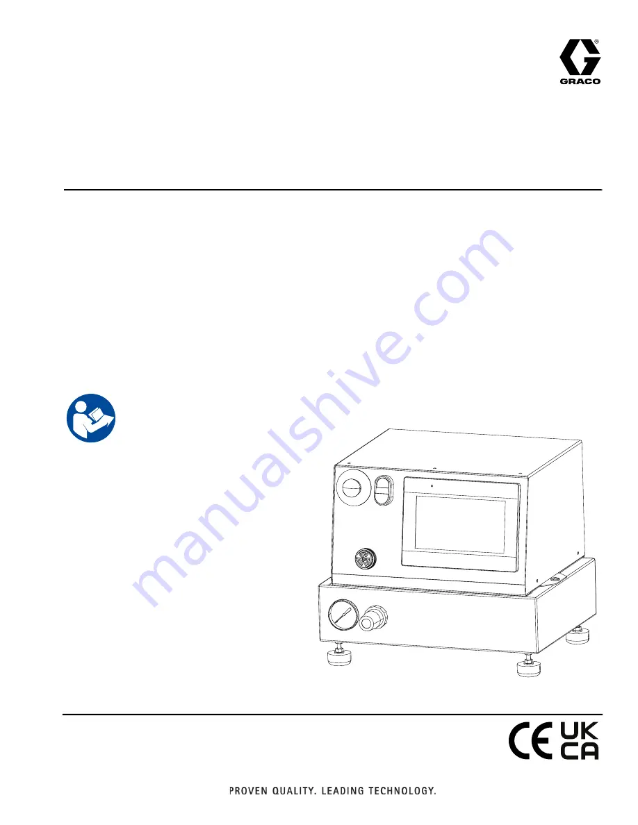
PD44

Control Box

Meter, mix and dispense system for two-component micro-dispensing of sealants and 

adhesives. For professional use only.

Not approved for use in explosive atmospheres or hazardous (classified) locations. 

26C940

Micrometer PD44 Control Box

100 psi (0.7 MPa, 7 bar) Maximum Air Working Pressure

See page for model information.

Important Safety Instructions

Read all warnings and instructions in this 

manual before using the equipment. 

Save these instructions. 

Summary of Contents for PD44

Page 1: ...fessional use only Not approved for use in explosive atmospheres or hazardous classified locations 26C940 Micrometer PD44 Control Box 100 psi 0 7 MPa 7 bar Maximum Air Working Pressure See page 2 for...

Page 2: ...ts 26 Schematics 27 Electrical Schematics 27 Pneumatic Schematic 30 Parts 31 Electrical Enclosure 31 Lower Pneumatic Enclosure 32 Technical Specifications 33 California Proposition 65 33 Graco Standar...

Page 3: ...s prevent serious injury including long term exposure inhalation of toxic fumes mists or vapors allergic reaction burns eye injury and hearing loss This protective equipment includes but is not limite...

Page 4: ...ords Ensure ground prongs are intact on power and extension cords PRESSURIZED EQUIPMENT HAZARD Fluid from the equipment leaks or ruptured components can splash in the eyes or on skin and cause serious...

Page 5: ...ts immediately with genuine manufacturer s replacement parts only Do not alter or modify equipment Alterations or modifications may void agency approvals and create safety hazards Make sure all equipm...

Page 6: ...eryone in the work area must wear appropriate respiratory protection Always wear a properly fitting respirator which may include a supplied air respirator Ventilate the work area according to instruct...

Page 7: ...erials flush the equipment multiple times to ensure it is thoroughly clean Always clean the fluid inlet strainers after flushing Check with your material manufacturer for chemical compatibility When c...

Page 8: ...Spool Valve Load Connection N Spool Valve Dispense Connection P Air Cylinder Extend Connection R Air Cylinder Retract Connection S Air Pressure Regulator T Air Pressure Gauge FIG 1 Micrometer PD44 Co...

Page 9: ...rdinances Air and fluid hoses use only electrically conductive hoses Fluid supply container follow local code Solvent pails used when flushing follow local code Use only conductive metal pails placed...

Page 10: ...5 3 4 6 1 7 2 5 3 4 6 1 1 2 5 6 3 7 12 9 13 10 14 11 8 4 SIGNAL CONNECTION PG 3 A TANK LEVEL CONTROLS PG 4 B TANK LEVEL CONTROLS PG 2 CUSTOMER I O 100V TO 250V AC PG 8 START MACHINE I O PG 1 1 3 4 2 E...

Page 11: ...ions The foot switch the Start button and the optional Customer Start Signal can be used to initiate shots These are referred to as start devices Perform a Shot 1 Navigate to the Posidot Control scree...

Page 12: ...een Screen Access Buttons All buttons on the main screen open a new specified screen For example pressing the Status button opens the Status screen FIG 6 Screen Navigation Diagram Main Screen PD44 Con...

Page 13: ...HMI Operation 313877J 13 Posidot Control Screen NOTE A 1 indicates the mode is ON A 0 indicates the mode is OFF FIG 8 Posidot Control Screen...

Page 14: ...ssed and held Continuous Mode The PD44 continually cycles the pumps when the start device is pressed Purge Timer On Off This enables On or disables Off the Purge Timer When the Purge Timer is enabled...

Page 15: ...volume set the timer for one half the gel time of the material If the shot size is smaller use the following formula to determine the Purge Timer setting For example with mixer volume 13 3cc shot siz...

Page 16: ...e bottom gray field shows the value of the Purge Timer in seconds as it times down Note when the Purge Timer times out and the PD44 cycles it will begin timing down again Alarm Timer When the Purge Ti...

Page 17: ...HMI Operation 313877J 17 Status Screen NOTE A 1 indicates the mode is ON A 0 indicates the mode is OFF FIG 10 Status Screen...

Page 18: ...als every 100 000 cycles when the Totalizer gets around 100 000 the seals can be replaced and the Totalizer reset PLC Program HMI Program Shows the software and revision level for both the PLC and HMI...

Page 19: ...HMI Operation 313877J 19 Level 1 Control Screen NOTE A 1 indicates the mode is ON A 0 indicates the mode is OFF FIG 11 Level 1 Control Screen...

Page 20: ...on When the audible alarm sounds because the material level is low in either tank pressing this button turns it off Message Description Material High The material level in the tank is at or above the...

Page 21: ...HMI Operation 313877J 21 Level 2 Control Screen NOTE A 1 indicates the mode is ON A 0 indicates the mode is OFF FIG 12 Level 2 Control Screen...

Page 22: ...til the audible alarm sounds if the tank material level does not reach the high level sensor If the high level sensor is activated before the Fill Timer times out the Fill Timer is reset The Fill Time...

Page 23: ...PD44 Control screen 2 Press the Retract button 3 Press the Extend button 4 Press the Control Power Switch B Ensure every thing is off 5 Perform the Pressure Relief Procedure 6 Perform feed system shut...

Page 24: ...life recycle it in a responsible manner Maintenance See the appropriate manuals for dispense valve and feed system maintenance schedules and procedures See Related Manuals on page 2 NOTE If material...

Page 25: ...d Flow control valve closed Open Dispense valve not discharging normal or full volume Low material level in reservoirs Fill material reservoirs and prime the machine Air in material tanks Fill reservo...

Page 26: ...e when pump is retracted and LS EXT is tripped Cycle Complete Output In Shot Mode changes state for one second after the retract switch is tripped Customer Start Input In any mode operates in parallel...

Page 27: ...Schematics 313877J 27 Schematics Electrical Schematics FIG 14...

Page 28: ...Schematics 28 313877J FIG 15...

Page 29: ...Schematics 313877J 29 FIG 16...

Page 30: ...Schematics 30 313877J Pneumatic Schematic FIG 17...

Page 31: ...ription Qty 521 81 1053 2 11 FUSE 5mm x 20mm 2A time delay 1 522 F0300011 RELAY master control 1 530 26D026 CONTROL PLC with program 1 532 24J189 POWER SUPPLY 24VDC 1 75A 120 240V 1 558 26D027 DISPLAY...

Page 32: ...matic Enclosure Lower Pneumatic Enclosure 637 636 Ref Part Description Qty 02 2891 7 50 LOWER BASE pneumatic components PD44 1 636 16M434 VALVE solenoid extend retract solenoid 1 637 83 0397 24D 11 VA...

Page 33: ...ssure 100 psi 0 7 MPa 7 bar Supplied Air Requirements 1 to 3 cfm at 80 psi to 100 psi Electrical Requirements 120 240V 50 60 Hz 0 6 amp 120V 0 3 amp 240V Fuses Required 5 x 20 mm 2A time delay Graco p...

Page 34: ...de at a reasonable charge which charges may include the costs of parts labor and transportation THIS WARRANTY IS EXCLUSIVE AND IS IN LIEU OF ANY OTHER WARRANTIES EXPRESS OR IMPLIED INCLUDING BUT NOT L...

Reviews: