308-444
17
Service
3.
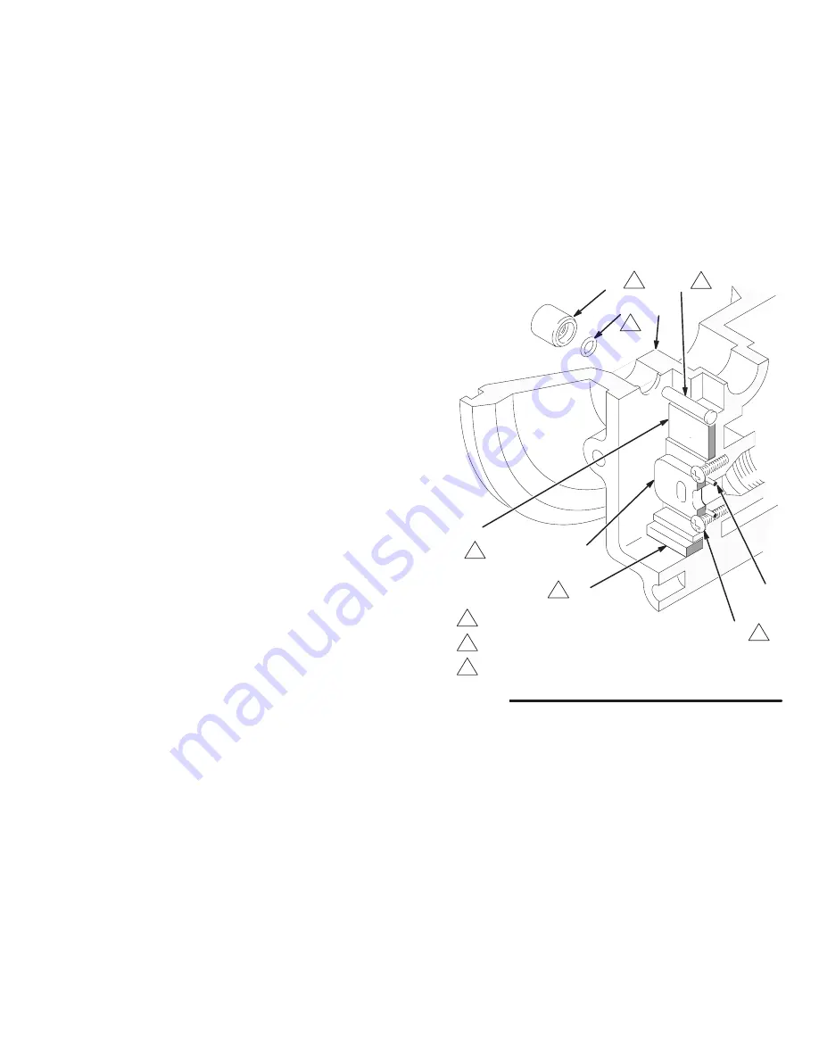
See Fig. 11. Use an o-ring pick to remove the
bearings (9 and 24).
4.
Remove the two screws (23) holding the valve
plate (13) to the pump. Use an o-ring pick to
remove the valve plate and seal (12). Clean and
inspect the parts. Replace any worn ones.
5.
If the pilot pins (26) are accessible from the inside
of the pump housing (1), pull them out. If not
accessible, disassemble the fluid section as ex-
plained on page 23.
NOTE: Inspect the pilot pin o-rings (28) and bearings
(27) in place. Removal will destroy the bearings and is
not required unless they are damaged. To service the
bearings, first perform steps 3 to 5 on page 23.
6.
Use a 1/8 in. EZY-OUT to remove the bearings
(27) from the housing (1). See Fig. 22 on page 25
for an illustration of how to use an EZY-OUT.
Remove the o-rings (28). Clean and inspect the
parts. Replace any worn ones.
NOTE: If the pilot pin o-rings (28) and bearings (27)
were not removed, go to step 8.
7.
Grease the o-rings (28) and install them in the
bearings (27). Press the bearings and o-rings in
place so the bearings are flush with the surface of
the housing (1). See Fig. 11.
8.
Grease the pilot pins (26) and install them from the
inside of the housing (1).
9.
Install the seal (12) in the pump housing (1). Install
the valve plate (13) and secure with the two
screws (23). (The heads of the screws overlap the
top and bottom edges of the plate to hold it in
place.) Torque the screws to 5 to 7 in-lb (0.6 to 0.8
N-m).
10. Apply grease (25 ) to the bearings (9 and 24).
Install the bearing (9 ) in the pump housing (1).
Install the other bearing (24).
11. Make certain the o-ring (19 ) is in place on the air
valve (A). See Fig. 10.
12. Apply grease (25 ) where shown in Fig. 10.
Fig. 11
3
Press-fit flush with surface of housing (1).
04233
1
1
Torque to 5 to 7 in-lb (0.6 to 0.8 N-m).
2
Apply grease (25 ).
1
2
2
2
2
3
27
28
26
12
23
9
13
24
Summary of Contents for Husky 715
Page 35: ...308 444 35 Notes...


