background image

308-188 7

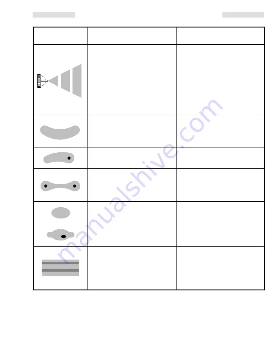
SPRAY PATTERN TROUBLESHOOTING CHART

PROBLEM:

CAUSE

SOLUTION 

IMPROPER SPRAY 
PATTERN

Insufficient fluid supply.

Adjust fluid regulator or fill fluid tank.

Loose fluid nozzle or damaged fluid 

Tighten or replace fluid nozzle (2) and  

nozzle taper seat. 

needle (1).

Dirt between fluid nozzle, taper seat 

Clean. 

and body.

Loose or cracked fluid inlet fitting (4a).

Tighten or replace fitting.

Loose fluid tube in pressure tank.

Tighten fluid tube.

Dry or worn fluid needle packings (10, 16) 

Lubricate or replace packings; 

or loose packing nuts (9) permit air to get 

tighten packing nuts.

into fluid passage.

Fluid build-up on air cap; partially 

Clean with soft implement or 

clogged horn holes. Full air pressure 

submerge in suitable solvent and  

from clean horn hole forces fan pattern 

wipe clean.

toward clogged end.

Damaged fluid nozzle or air cap holes.

Replace damaged part.

Fluid build-up on the perimeter of fluid 

Remove obstruction. Never use wire 

nozzle orifice, or partially clogged fluid 

or hard instruments.

nozzle orifice.

Too high atomization air pressure.

Reduce air pressure or adjust air 
adjusting valve (5).

Fluid too thin.

Regulate fluid viscosity.

Not enough fluid pressure.

Increase fluid pressure.

Low atomization air pressure.

Increase air pressure or adjust air 
adjusting valve (5).

Fluid too thick.

Regulate fluid viscosity.

Too much fluid.

Reduce fluid pressure.

Adjust fluid adjusting valve (6) until 
proper pattern is obtained.

Last coat of fluid applied too wet.

Apply drier finish with multiple 
strokes.

Too much air pressure.

Use least air pressure necessary.

Insufficient air pressure.

Increase air pressure.

Non-uniform spray pattern.

Clean or replace air cap.

Fluttering or spitting
spray

Streaks

NOTE: Some improper patterns are caused by the improper balance between air and fluid.

Summary of Contents for H.E.L.P. 1600B

Page 1: ...es sure the gun was designed to operate safely under The Maximum Operating Air Pressure is the maximum inlet air pressure allowable to guarantee HVLP compliance If input pressures are maintained at or...

Page 2: ...em Fluid Compatibility BE SURE all fluids and solvents used are chemically compatible with the Wetted Parts shown in the TECH NICAL DATA on the back cover Always read the fluid and solvent manufacture...

Page 3: ...w regulations The Typical Installation shown above is only a guide for selecting and installing the equipment needed for an au tomatic spray system It is not an actual system design For assistance in...

Page 4: ...hen check the viscos ity of your fluid This gun is best suited for light to medium fluids Light Fluid 19 to 24 seconds No 2 Zahn cup Auto Furniture Appliances Fine Finish Metallics Top Coats Lacquer E...

Page 5: ...achieved Always use the low est possible atomizing air pressure to obtain the de sired results To Operate the Gun Adjust the system s sensing device so the gun starts spraying just before meeting the...

Page 6: ...th a fine bristled brush provided with the gun 4 To clean out air cap holes use a soft implement such as a toothpick to avoid damaging critical surfaces Clean the air cap and fluid nozzle daily minimu...

Page 7: ...clogged end Damaged fluid nozzle or air cap holes Replace damaged part Fluid build up on the perimeter of fluid Remove obstruction Never use wire nozzle orifice or partially clogged fluid or hard ins...

Page 8: ...ocedure Warning on page 6 to relieve fluid pressure 2 Unscrew and remove the fluid needle guide 8 3 Carefully pull the fluid needle 1 out of the piston 12 4 Unscrew the packing nuts 9 and remove the p...

Page 9: ...replacing CYL air fitting 4b not shown here see Parts Drawing apply Loctite PST Pipe Sealant or equivalent PACKING DETAIL 10 PACKING DETAIL 16 0898 0900 Lubricate periodically with light grease DIMENS...

Page 10: ...ES for other sizes 1 3 110 864 AIR CAP 1 4 223 282 GUN BODY Includes items 4a 4b 1 4a 106 786 FITTING fluid includes gasket washer 1 4b 106 690 FITTING air 1 4c 185 771 LABEL instruction 1 5 107 824 V...

Page 11: ...ONNECTOR elbow 1 8 npt m 1 2d 104 192 COUPLING pipe 1 8 npt f 1 2e 102 730 GAUGE 0 to 15 psi 0 to 1 bar pressure range 1 AIR FILTER MOISTURE SEPARATOR 250 psi 17 5 bar MAXIMUM WORKING PRESSURE For cle...

Page 12: ...ment or materials not supplied by Graco This warranty is conditioned upon the prepaid return of the equipment claimed to be defective to an authorized Graco distributor for verification of the claimed...

Reviews: