background image

5

309407

Installation

NOTE:

 Reference numbers and letters in parentheses

in the text refer to the callouts in the figures and the
parts drawing.

NOTE:

 Always use Genuine Graco Parts and

Accessories, available from your Graco distributor.

Grounding

WARNING

FIRE AND EXPLOSION HAZARD

Before operating the pump, ground the
system as explained below. Also read
the section

 FIRE OR EXPLOSION HAZ-

ARD

 on page 3.

D

Pump:

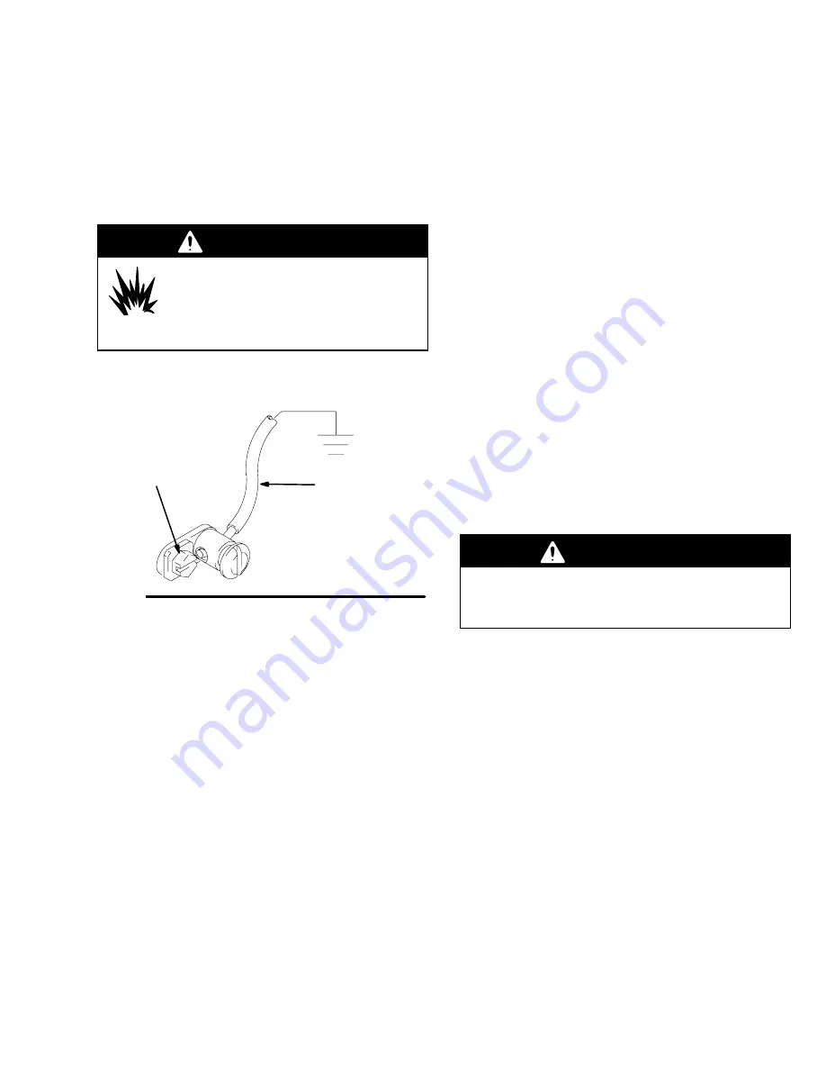
  Use a ground wire and clamp as shown

below.

Fig. 1

TI1052

Y

Z

D

Air and fluid hoses:

  Use only electrically conductive

hoses.

D

Air compressor:

  Follow manufacturer’s

recommendations.

D

Dispensing valve:

  Ground through connection to a

properly grounded fluid hose and pump.

D

Object being dispensed to:

  Follow your local code.

D

Solvent pails used when flushing:

  Follow your local

code. Use only metal pails, which are conductive,
placed on a grounded surface. Do not place the pail
on a nonconductive surface, such as paper or
cardboard, which interrupts the grounding
continuity.

D

To maintain grounding continuity when flushing or
relieving pressure

, hold a metal part of the

dispensing gun firmly to the side of a grounded

metal

 pail, then trigger the gun to ground the pump.

To ground the pump, 

remove the ground screw (Z)

and insert through the eye of the ring terminal at end of
ground wire (Y). Fasten the ground screw back onto
the pump and tighten securely. Connect the other end
of the ground wire to a true earth ground. See Fig. 1.

To order a ground wire and clamp, order Part No.
222011.

Mounting the Pump

WARNING

Mount the pump securely so that it cannot move
around during operation.  Failure to do so could
result in personal injury or equipment damage.

D

Select a convenient location for the equipment to
ensure easy operator access to the pump air
controls, sufficient room to change supply
containers, and a secure mounting platform.

D

If you are mounting the pump directly on the supply
tank, position the pump so its intake valve is no
more than 1 in. (25 mm) from the bottom of the
container.  Mount the pump to the cover or other
suitable mounting device.

Summary of Contents for fire-ball 425

Page 1: ...ure Model No 965124 Series B Stubby length Model No 965129 Series B 400 lb 180 Kg drum length For Closed Drum Mounting 309407E EN Important Safety instructions Read all warnings and instructions in th...

Page 2: ...ke just a cut but it is a serious injury that can result in amputation Get immediate surgi cal treatment D Do not point the dispensing device at anyone or any part of the body D Do not put your hand o...

Page 3: ...e 1 1 1 trichloroethane methylene chloride other halogenated hydrocarbon solvents or fluids containing such solvents in pressurized aluminum equipment Such use could result in a chemical reaction with...

Page 4: ...nt or in the Technical Data for your equipment Do not exceed the maximum working pressure of the lowest rated component in your system D Use fluids and solvents which are compatible with the equipment...

Page 5: ...dboard which interrupts the grounding continuity D To maintain grounding continuity when flushing or relieving pressure hold a metal part of the dispensing gun firmly to the side of a grounded metal p...

Page 6: ...control pump speed WARNING A bleed type master air valve B is required to shut off and relieve air pressure that may be trapped in the air motor Trapped air could cause the pump to cycle unexpectedly...

Page 7: ...itting coupler is clogged or that pressure has not been fully relieved after following the steps above VERY SLOWLY loosen the coupler or hose end coupling and relieve pressure gradually then loosen co...

Page 8: ...r damaged air motor gasket packing seal etc Service air motor Erratic pump operation Exhausted fluid supply Refill and reprime or flush p p p Held open or worn intake valve or piston packings Clear se...

Page 9: ...9 309407 Notes...

Page 10: ...10 309407 Service TI2148A Fig 3 12 11 6 25 15 2 31 3 14 4 30 16 5 7 8 9 10...

Page 11: ...rod 3 unscrew valve housing 14 from piston housing 16 8 Remove washers 35 spreaders 34 cup packings 36 o ring 33 and cup spacer 20 from the piston housing 16 9 Clean and inspect all the parts Reassemb...

Page 12: ...ment This pump has an adjustable piston ball check To change the piston ball travel loosen the locknut 4 Turn the piston valve housing 14 counterclockwise to increase and clockwise to decrease Medium...

Page 13: ...13 309407 Notes...

Page 14: ...14 309407 Parts TI2147A 1 13 12 3 4 14 15 35 34 36 33 20 36 34 35 16 8 2 31 5 30 6 11 7 9 10 Packing vee Spacer...

Page 15: ...cotter 1 13 156641 O RING 1 14 624941 HOUSING valve 1 15 100279 BALL metallic 1 16 624942 HOUSING valve piston 1 20 158857 SPACER cup 1 Ref No Part No Description Qty 30 603778 PACKING foot valve 2 31...

Page 16: ...3 9 in 724 mm 353 mm 14 6 in 371 mm 1 2 npt f Air Inlet TI2146A Model 965124 Model 965129 37 3 in 947 4 mm Model 965124 Model 965129 50 8 in 1290 mm Mounting Hole Layout 06337 3 1 4 82 6 mm DIA TWO 5...

Page 17: ...onsumption approx 13 cfm per gallon 6 m hr liter of fluid at 100 psi 0 7 MPa 7 bar Wetted parts steel brass aluminum leather Buna N Weight 38 lb 17 kg Sound Pressure Level measured at 1 meter from uni...

Page 18: ...uyer agrees that no other remedy including but not limited to incidental or consequential damages for lost profits lost sales injury to person or property or any other incidental or consequential loss...

Reviews: