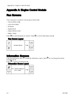
Appendix A: Engine Control Module
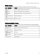
Mode Icons
An icon is displayed in the mode icon area of the display to indicate what mode the unit is currently in.
Icon
Description
Details
Stopped
Engine is at rest and the unit is in stop mode.
Auto
Engine is at rest and the unit is in auto mode.
Manual
Engine is at rest and the unit is in manual run mode.
Timer animation
Engine is starting up.
Running animation
Engine is running.
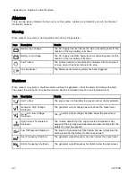
Instrumentation Icons
A small icon is displayed in the instrumentation icon area to indicate what value is currently being displayed.
Icon
Description
Details
Generator
Generator voltage and frequency screen
Engine Speed
Engine speed screen
Engine Lifetime
Counter
Hours run
Event Log
Event is being displayed.
Unit Time
Unused feature
3A1705E
91
Summary of Contents for 259079
Page 34: ...Setup A5 A1 A2 AS AN A3 AT A3 A4 A2 A6 A4 34 3A1705E...
Page 45: ...Advanced Display Module ADM Operation Setup Screens Navigation Diagram Figure 35 3A1705E 45...
Page 49: ...Advanced Display Module ADM Operation Run Screens Navigation Diagram Figure 36 3A1705E 49...
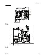
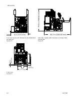
Page 93: ...Dimensions Dimensions Top View Figure 43 Side View Figure 44 3A1705E 93...
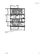
Page 95: ...Dimensions Pallet Mounting Dimensions Figure 48 3A1705E 95...
Page 97: ...Notes Notes 3A1705E 97...

