


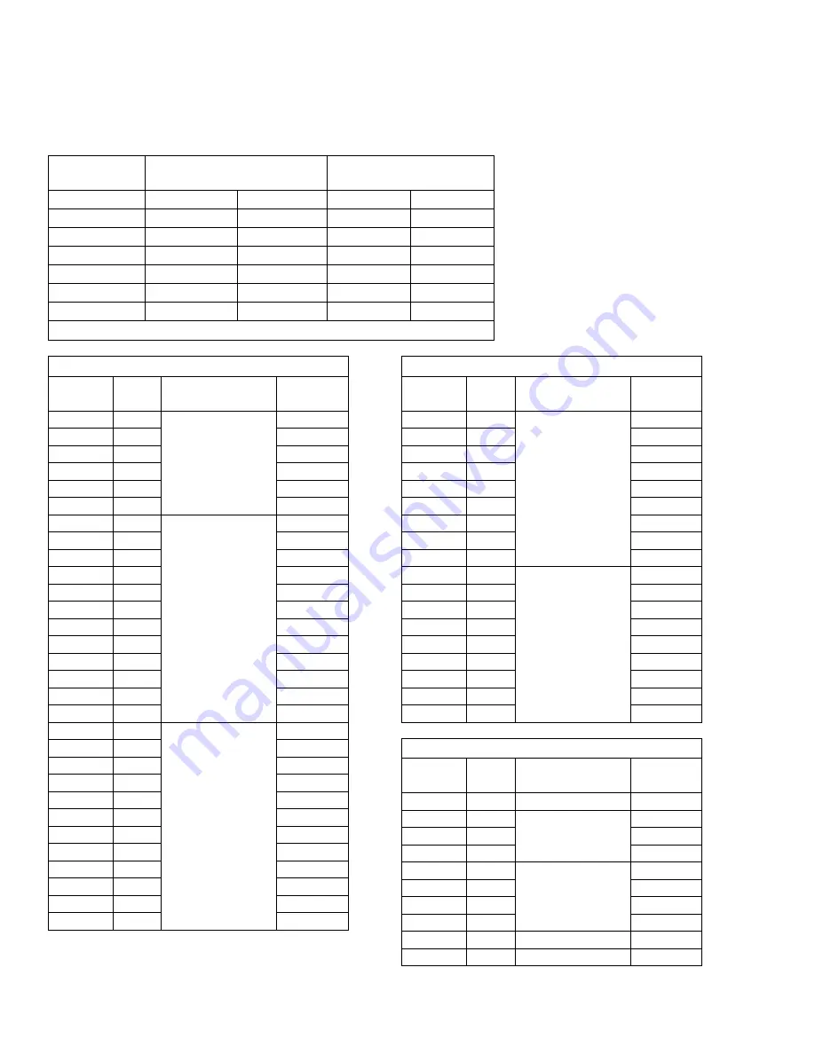
Cleaning Drill Chart
26
313267W
Cleaning Drill Chart
Round Mixing
Chamber
Mixing Chamber Nozzle
Cleaning Drill
Mixing Chamber Hole
Cleaning Drill
GC250A
248891
0.033
276984
0.022
GC2500
GC0083
0.049
GC0080
0.035
GC2501
249112
0.057
246629
0.042
GC2502
GC0069
0.071
256628
0.052
GC2503
246625
0.086
246627
0.059
GC2504
246624
0.094
296297
0.067
GC2505
246623
0.116
246625
0.086
Drill Pin Vise 117661
Short Version
Part
FAN
Code
Spray Width
in. (mm)
Orifice
Diameter
GC2573
215
2-4 (50.8-101.6)
0.015
GC2575
217
0.017
GC2578
221
0.021
GC2582
223
0.023
GC2589
231
0.031
GC2592
235
0.035
GC2623
411
8-10 (203.2-254)
0.011
GC2624
413
0.013
GC2574
415
0.015
GC2576
417
0.017
GC2625
419
0.019
GC2579
421
0.021
GC2583
423
0.023
GC2626
425
0.025
GC2586
427
0.027
GC2590
431
0.031
GC2593
435
0.035
GC2595
439
0.039
GC2627
511
10-12 (254-304.8)
0.011
GC2628
513
0.013
GC2629
515
0.015
GC2577
517
0.017
GC2630
519
0.019
GC2580
521
0.021
GC2584
523
0.023
GC2631
525
0.025
GC2587
527
0.027
GC2591
531
0.031
GC2594
535
0.035
GC2596
539
0.039
GC2632
611
12-14 (304.8-355.6)
0.011
GC2633
613
0.013
GC2634
615
0.015
GC2635
617
0.017
GC2636
619
0.019
GC2637
621
0.021
GC2638
623
0.023
GC2639
625
0.025
GC2640
627
0.027
GC2641
711
14-16 (355.6-406.4)
0.011
GC2642
713
0.013
GC2643
715
0.015
GC2644
717
0.017
GC2645
719
0.019
GC2646
721
0.021
GC2585
723
0.023
GC2647
725
0.025
GC2648
727
0.027
Long Version
Part
FAN
Code
Spray Width
in. (mm)
Orifice
Diameter
GC2599
351
6-8 (152.4-203.2)
0.051 in.
GC2600
451
8-10 (203.2-254)
0.051 in.
GC2604
461
0.061 in.
GC2607
471
0.071 in.
GC2597
543
10-12 (254-304.8)
0.043 in.
GC2601
551
0.051 in.
GC2605
561
0.061 in.
GC2608
571
0.071 in.
GC2606
661
12-14 (304.8-355.6)
0.051 in.
GC2602
751
14-16 (355.6-406.4)
0.061 in.
Short Version
Part
FAN
Code
Spray Width
in. (mm)
Orifice
Diameter


