


Operation and Instruction Manual
for
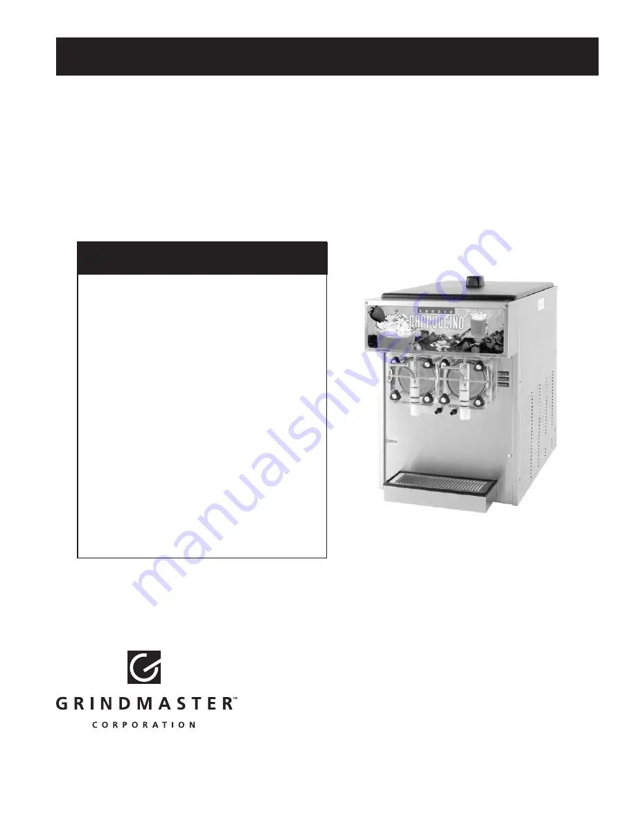
Models 5512 & 5512E
Crathco
®
Beverage Freezers
Operator’s Safety Precautions . . . . . . . . . . . . .3
Installation . . . . . . . . . . . . . . . . . . . . . . . . . . .3-5
Operation . . . . . . . . . . . . . . . . . . . . . . . . . . .6-8
Product Tips . . . . . . . . . . . . . . . . . . . . . . . . .8-9
Consistency Control . . . . . . . . . . . . . . . . . .9-10
Care & Cleaning . . . . . . . . . . . . . . . . . . . .11-15
Maintenance . . . . . . . . . . . . . . . . . . . . . . .15-16
Adjustments . . . . . . . . . . . . . . . . . . . . . . . . . .17
Freezer Specifications . . . . . . . . . . . . . . . .18-19
Troubleshooting Guide . . . . . . . . . . . . . . .20-21
Exploded Views . . . . . . . . . . . . . . . . . . . . .22-30
Wiring Diagrams . . . . . . . . . . . . . . . . . . . .31-41
Refrigeration Schematic . . . . . . . . . . . . . . . . .42
Grindmaster Corporation
4003 Collins Lane
Louisville, KY 40245-1643
Phone (502) 425-4776
800-695-4500 (USA & Canada only)
(800) 568-5715 (technical service only)
Fax (502) 425-4664
www.grindmaster.com
TABLE OF CONTENTS
0106 Form #WH-332-04
Part #W0600138
© Grindmaster Corporation, 2000
PRINTED IN USA
Model 5512
Prior authorization must be obtained from
Grindmaster Corporation for all warranty
claims.
Summary of Contents for Crathco 5512
Page 2: ......
Page 33: ...Crathco 5512 Manual Page 33 Model 5512 Electrical Components Front Electrical Box ...
Page 34: ...Page 34 Crathco 5512 Manual Model 5512 E Electrical Components Front Electrical Box ...
Page 38: ...Page 38 Crathco 5512 Manual Model 5512 Ladder Diagram ...
Page 39: ...Crathco 5512 Manual Page 39 Model 5512 E Ladder Diagram ...
Page 42: ...Page 42 Crathco 5512 Manual Models 5512 5512 E Refrigeration Schematic ...
Page 43: ......


