background image

SAFETY WARNINGS

FOR PROFESSIONAL USE ONLY.


OBSERVE ALL WARNINGS.

 Read And Understand All Instruction Manuals Before Operating Equipment.

EQUIPMENT MISUSE HAZARD

General Safety

Any misuse of the equipment or accessories, such as overpressurizing,

modifying parts, using incompatible chemicals and fluids, or using worn

or damaged parts, can cause them to rupture and result in serious bodily

injury, including eye injury, or fire, explosion or property damage.

NEVER alter or modify any part of this equipment; doing so could cause it

to malfunction.

CHECK all equipment regularly and repair or replace worn or damaged

parts immediately.

Take precautions to avoid a toxic fluid spill. See 

TOXIC FLUID HAZARD

,

below.

System Pressure

This pump develops 8 bar (120 psi) MAXIMUM WORKING PRESSURE

at 8 bar (120 psi) incoming air pressure. NEVER exceed 8 bar (120 psi)

air pressure to the pump. DO NOT exceed the maximum working pres-

sure of any component or accessory used in the system.

Fluid Compatibility

BE SURE that all fluids and solvents used are chemically compatible with

the wetted parts shown in the 

TECHNICAL DATA

 on the back page. Al-

ways read the manufacturer’s literature before using fluid or solvent in

this pump.

TOXIC FLUID HAZARD

Improper handling of toxic fluids or inhaling toxic vapors can cause ex-

tremely serious bodily injury, even death, due to splashing in the eyes,

ingestion, or bodily contamination. Know what fluid you are pumping and

its specific hazards. Store toxic fluid in an appropriate, approved con-

tainer. Dispose of it according to all Local, State and Federal guidelines

for toxic fluids. Be sure to observe all the following precautions when han-

dling known or potentially toxic fluids.

1.

Always wear appropriate clothing and equipment, such as eye pro-

tection and breathing apparatus, to protect yourself.

2.

Be sure to pipe and dispose of the exhaust air safely . If the dia-

phragm fails, the fluid will be exhausted along with the air.

3.

Be sure to secure the fluid outlet hose tightly into the receiving con-

tainer to prevent it from coming loose and improperly draining the

fluid.

SUCTION HAZARD

NEVER place your hands on or near the pump suction inlet. Powerful

suction could cause serious bodily injury.

FIRE OR EXPLOSION HAZARD

Static electricity is created by the flow of fluid through the pump and hose.

If every part of the equipment is not properly grounded, sparking may oc-

cur, and the system may become hazardous. Sparking may also occur

when plugging in or unplugging a power supply cord. Sparks can ignite

fumes from solvents and the fluid being pumped, dust particles and other

flammable substances, whether you are pumping indoors or outdoors,

and can cause a fire or explosion and serious bodily injury and property

damage. Do not plug in or unplug any power supply cords in the pumping

area when there is any chance of igniting fumes still in the air.

If you experience any static sparking or even a slight shock while using

this equipment, 

STOP PUMPING IMMEDIATELY.

 Check the entire sys-

tem for proper grounding. Do not use the system again until the problem

has been identified and corrected.

Grounding

To reduce the risk of static sparking, ground the pump and all other spray

equipment used or located in the spray area. CHECK your local electrical

code for detailed grounding instructions for your area and type of equip-

ment. BE SURE to ground all of this spray equipment:

1.

Pump: use a ground wire and clamp as shown in Fig 1.

2.

Air and fluid hoses: use only grounded hoses with a maximum of

150 m (500 ft) combined hose length to ensure grounding continuity.

3.

Air compressor: according to the manufacturer ’s recommenda-

tions.

4.

All solvent pails used when flushing, according to local code. Use

only metal pails, which are conductive. Do not place the pail on a

nonconductive surface, such as paper or cardboard, which inter-

rupts the grounding continuity.

5.

Fluid supply container: according to your local code.
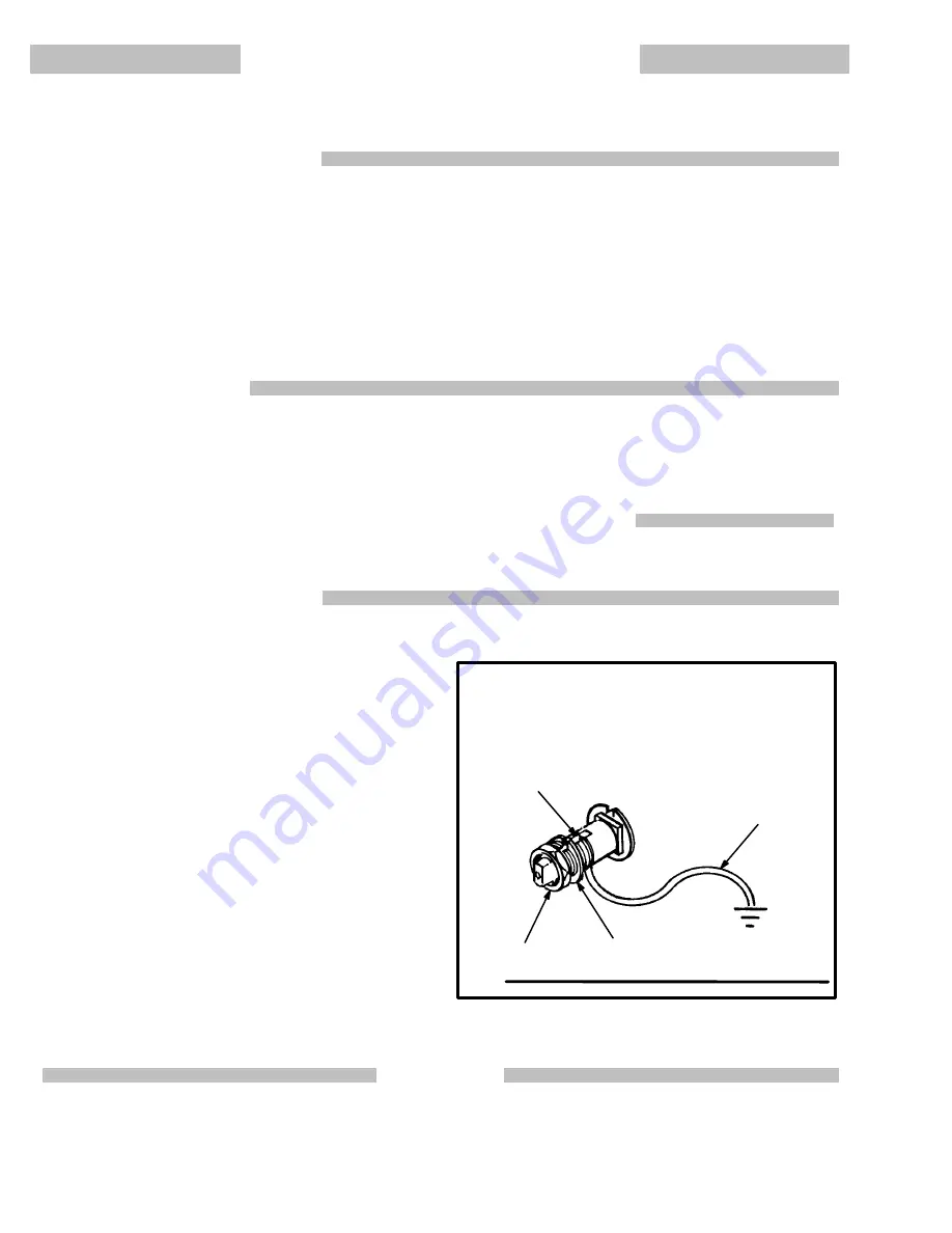
To ground the pump:

To ground the pump, loosen the grounding lug locknut (W) and

washer (X). Insert one end of a 1.5 mm

@

 (12 ga) minimum ground

wire (Y) into the slot in lug (Z) and tighten the locknut securely. See

Fig 1. Connect the clamp end of the wire to a true earth ground. Refer

to ACCESSORIES on page 20 to order a ground wire and clamp.

Fig 1

W

X

Y

Z

IMPORTANT

United States Government safety standards have been adopted under the Occupational Safety and Health Act. These standards – particularly the Gen-

eral Standards, Part 1910, and the Construction Standards, Part 1926 – should be consulted.

Summary of Contents for 218-940

Page 1: ...agram 21 Pump Performance Data 22 23 Technical Data Back Cover Warranty Back Cover The HUSKY 1030 DIAPHRAGM PUMP 8 bar 120 psi MAXIMUM WORKING PRESSURE ALUMINUM MODELS Model 218 940 Series D With Buna...

Page 2: ...ion inlet Powerful suction could cause serious bodily injury FIRE OR EXPLOSION HAZARD Static electricity is created by the flow of fluid through the pump and hose If every part of the equipment is not...

Page 3: ...oils water or ganic acids aldehydes amines Halogenated hydrocarbons hydrocar bons silicate esters ethers animal oils vegetable oils Polyester Elastomer 0 100_C 32 212_F Excellent resistance to alcoho...

Page 4: ...ed Transfer Hose K Fluid Outlet L Suction Hose M Fluid Inlet P Air Control Valve Y Ground Wire F C K J A D A G P E M Y B H L FLUID OUTLET FLUID INLET FLUID INLET GROUNDED AIR HOSE REQUIRED MUFFLER P N...

Page 5: ...nd the pump will not operate NOTE The inlet and outlet manifolds can be removed and turned 180 _ to change the direction the ports face Refer to Repairing the Check Valves on page 11 for the procedure...

Page 6: ...slowly until all air has been pushed out of the lines Then open the air control valve only as far as necessary to get the desired results WARNING NEVER exceed 8 bar 120 psi air supply pressure to the...

Page 7: ...ee page 8 Pump operates erratically Clogged or leaking suction line Inspect for leaks or clear Sticky air director valve 52 Check See page 8 Sticky check valve balls 19 Clean or repair See page 11 Dia...

Page 8: ...of the pump housing 2 Remove the valve caps 30 and 33 3 Use a 5 mm hex key wrench to remove the screws 39 from the valve block 32 Then remove the air inlet gasket 38 and plate 37 4 Unscrew the actuato...

Page 9: ...the plate and pump housing 2 Install a screw 35 and washer 36 to check the alignment adjust as necessary Loosely install a screw and washer in the opposite corner Then install the remaining screws an...

Page 10: ...let manifold 21 5 Remove the bolts 14 3 or 55 legs 12 or 13 washers 16 and nuts 15 from the diaphragm cov ers 11 on each side of the pump 6 Hold the fluid side support plate 8 on one end of the pump a...

Page 11: ...20 ft lb 16 Be sure the mating surfaces of the pump housing and the manifolds are clean 17 Working on the inlet side bottom first arrow on dia phragm cover will face down install an o ring 17 ball 19...

Page 12: ...8 5 9 5 N m 6 2 7 ft lb TORQUE TO 13 5 16 N m 9 8 12 ft lb TORQUE TO 6 8 7 9 N m 5 5 8 ft lb TORQUE TO 42 47 N m 30 35 ft lb TORQUE TO 13 5 16 N m 9 8 12 ft lb TORQUE TO 13 5 16 N m 9 8 12 ft lb TORQU...

Page 13: ...EW socket M4 x 20 4 23 108 257 PLATE slide valve 1 24 108 260 GASKET slide valve 1 25 108 261 VALVE slide 1 26 108 262 SPRING air valve 1 27 108 268 PIN actuator air valve 1 28 108 267 SPOOL valve pil...

Page 14: ...8 5 9 5 N m 6 2 7 ft lb TORQUE TO 13 5 16 N m 9 8 12 ft lb TORQUE TO 6 8 7 9 N m 5 5 8 ft lb TORQUE TO 42 47 N m 30 35 ft lb TORQUE TO 13 5 16 N m 9 8 12 ft lb TORQUE TO 13 5 16 N m 9 8 12 ft lb TORQ...

Page 15: ...sst 1 22 108 254 SCREW socket M4 x 20 4 23 108 257 PLATE slide valve 1 24 108 260 GASKET slide valve 1 25 108 261 VALVE slide 1 26 108 262 SPRING air valve 1 27 108 268 PIN actuator air valve 1 28 108...

Page 16: ...ft lb TORQUE TO 42 47 N m 30 35 ft lb TORQUE TO 13 5 16 N m 9 8 12 ft lb TORQUE TO 27 N m 20 ft lb TORQUE TO 27 N m 20 ft lb 13 16 51 CHAMFERED SIDE FACES BALL 53 44 7 55 3 55 23 22 24 25 26 32 29 29...

Page 17: ...CK VALVE REPAIR KIT Must be purchased separately 220 988 r PTFE Consists of Ref No Qty 17 8 19 4 REF PART DESCRIPTION QTY NO NO 26 108 262 SPRING air valve 1 27 108 268 PIN actuator air valve 1 28 108...

Page 18: ...lb TORQUE TO 42 47 N m 30 35 ft lb TORQUE TO 13 5 16 N m 9 8 12 ft lb TORQUE TO 27 N m 20 ft lb TORQUE TO 27 N m 20 ft lb 7 13 CHAMFERED SIDE FACES BALL 33 51 53 16 44 55 55 3 23 22 24 25 26 32 29 29...

Page 19: ...261 VALVE slide 1 CHECK VALVE REPAIR KIT Must be purchased separately 220 988 r PTFE Consists of Ref No Qty 17 8 19 4 REF PART DESCRIPTION QTY NO NO 26 108 262 SPRING air valve 1 27 108 268 PIN actuat...

Page 20: ...when closed 1 2 npt m x f inlet and outlet STAINLESS STEEL BALL CONVERSION KIT 220 987 The stainless steel balls in this kit are heavier than the standard balls supplied in the pump and will seat posi...

Page 21: ...ight Leg DELETED 50 110 033 Bolt DELETED 54 108 577 Washer Models OLD 108 245 Plate 220 434 NEW 8 110 280 Plate 220 435 OLD 108 585 Left Leg 220 436 NEW 12 185 409 Left Leg OLD 108 586 Right Leg NEW 1...

Page 22: ...psi at a specific fluid flow lpm gpm and operating air pressure bar psi 1 Locate desired flow along bottom of chart 2 Follow vertical line up to intersection with selected fluid outlet pres sure curve...

Page 23: ...lpm gpm and operating air pressure bar psi 1 Locate desired flow along bottom of chart 2 Follow vertical line up to intersection with selected fluid outlet pres sure curve black Follow left to scale a...

Page 24: ...n manufacture installation operation or maintenance of structures accessories equipment or materi als not supplied by Graco This warranty is conditioned upon the prepaid return of the equipment claime...

Reviews: