


9
Step 9: Rail Attachment to Table Assembly
Parts Needed:
3- Rail Assemblies
WARNING: The Rail End may become damaged
if the Rail is allowed to sag down while one end
is attached to the Take-Up Rail Mount End,
or Front Rail Mount End.
9-1: Slide one side of the Ratchet Wheel of the Rail
Assembly into the wide slots in the Right Take-Up Rail
Mount End and snap it into place past the ratchet keeps.
As shown in Fig (9-1).
9-2: Slide the other side of the Ratchet Wheel of the Rail Assembly into the wide
slots in the Left Take-Up Rail Mount End and snap it into place. The rail should now
turn freely.
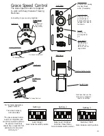
9-3: Put the Ratchet lever in the Neutral Position to roll the rails freely or Ratcheting
Position to ratchet the Rails, as shown in Fig(9-2).
Fig (9-1)
Fig (9-2)
Fig (10-1)
Ratcheting
Position
Neutral
Position
Step 10: Top Plate Assembly
Parts Needed:
1- Top Plate
1- Handle Brace
1- Right Handle Tube
1- Left Handle Tube
4- 6mm X 10 mm SBHS Screws
6- 6mm Hex Nuts
2- 6mm X 40mm SBHS Screws
Tools Required:
4mm Allen Wrench
Open End Wrench
Step 8: Rail Mount End Assembly
Parts Needed:
1- Left Take-Up Rail Mount End
1- Right Take-Up Rail Mount End
1- Right Front Rail Mount End
1- Left Front Rail Mount End
8- 6mm X 10 mm SBHC Screws
4- Plastic Knobs
Tools Required:
4mm Allen Wrench
8-1: Attach the Right & Left Take-Up
Rail Mount Ends to each side of the
Take-Up Fixtures with the four (4)
plastic knob. As shown in Fig (8-1).
8-2: Secure the Right & Left Front Rail Mount Ends to each side of the Frame End
Sub-Assembly by tightening four (4) 6mmX10mm SBHC Screws with the 4mm
Allen Wrench as shown in Fig (8-2).
Fig (8-1)
Take-Up Rail
Mount End
Fig (8-2)
Left Side of Frame
Front Rail
Mount End


