background image

3

Safety Instructions

10.  Ventilation-Slots and openings in the cabinet are provided for ventilation and to ensure reliable operation of the product and to protect it

from overheating. These openings must not be blocked or covered. The openings should never be blocked by placing the product on a
bed, sofa, rug, or other similar surface. This product should not be placed in a built-in installation such as a bookcase or rack unless proper
ventilation is provided or the manufacturer’s instructions have been adhered to.

11.  Power Sources-This product should be operated only from the type of power source indicated on the marking label. If you are not sure of

the type of power supplied to your home, consult your product dealer or local power company. For products intended to operate from
battery power, or other sources, refer to the operating instructions.

12.  Grounding or Polarization-This product may be equipped with a polarized alternating-current line plug (a plug having one blade wider

than the other). This plug will fit into the power outlet only one way. This is a safety feature. If you are unable to insert the plug fully into the
outlet, try reversing the plug. If the plug should still fail to fit, contact your electrician to replace your obsolete outlet. Do not defeat the safety
purpose of the polarized plug.

13.

Alternate Warnings -This product is equipped with a three-wire grounding-type plug, a plug having a third (grounding) pin. 
This plug will only fit into the outlet, contact your electrician to replace your obsolete outlet. Do not defeat the safety
purpose of the grounding-type plug. 

14.  Power-Cord Protection-Power-supply cords should be routed so that they are not likely to be walked on or pinched by items placed upon

or against them, paying particular attention to cords at plugs, convenience receptacles,
and the point where they exit from the product.

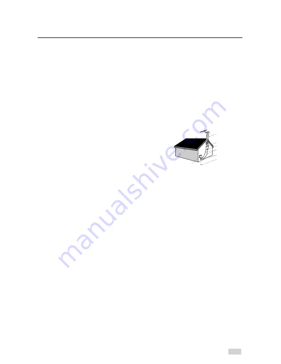
15.  Outdoor Antenna Grounding-If an outside antenna or cable system is connected to

the product, be sure the antenna or cable system is grounded so as to provide some
protection against voltage surges and built-up static charges. Section 810 of the
National Electrical Code, ANSI/NFPA 70 provides information with regard to proper
grounding of the mast and supporting structure, grounding of the lead-in wire to an
antenna discharge unit, size of grounding conductors, location of antenna-discharge unit,
connection to grounding electrodes, and requirements for the grounding electrode.

16.  Lightning-For added protection for this product during a lightning storm or when it is

left unattended and unused for long periods of time, unplug it from the wall outlet and disconnect the antenna or cable system. This will
prevent damage to the product due to lightning and power-line surges.

17.  Power Lines-An outside antenna system should not be located in the vicinity of overhead power lines or other electric light or power

circuits, or where it can fall into such power lines or circuits. When installing an outside antenna system, extreme care should be taken to
keep from touching such power lines or circuits as contact with them might be fatal.

18.  Overloading-Do not overload wall outlets, extension cords, or integral convenience receptacles as this can result in a risk of fire or electric

shock.

19.  Object and Liquid Entry-Never push objects of any kind into this product through openings as they may touch dangerous voltage points or

short-out parts that could result in a fire or electric shock. Never spill liquid of any kind on the product.

20.   Servicing-Do not attempt to service this product yourself as opening or removing covers may expose you to dangerous voltage or other

hazards. Refer all servicing to qualified service personnel.

21.   Damage Requiring Service-Unplug this product from the wall outlet and refer servicing to qualified service 

personnel under the following conditions:
When the power-supply cord or plug is damaged.
If liquid has been spilled or objects have fallen into the product. 
If the product has been exposed to rain or water.
If the product does not operate normally by following the operating instructions. Adjust only those controls that are  covered by the

operating instructions as an improper adjustment of other controls may result in damage and will often require extensive work by a
qualified technician to restore the product to its normal operation.

If the product has been dropped or damaged in any way.
f

When the product exhibits a distinct change in performance-this indicates a need for service.

22.  Replacement Parts-When replacement parts are required, be sure the service technician has used replacement parts specified by the

manufacturer or that have the same characteristics as the original part.Unauthorized substitutions may result in fire, electric shock, or other
hazards.

23.  Safety check-Upon completion of any service or repairs to this product, ask the service technician to perform safety checks to determine

that the product is in proper operating condition.

24.  Heat-The product should be situated away from heat sources such as radiators, heat registers, stoves, or other products (including

amplifiers) that produce heat.

25.

Wall or Ceiling Mounting The product should be mounted to a wall or ceiling only as recommended by the manufacturer.

Antenna Lead-in Wire

Ground Clamp
Antenna Discharge Unit
(NEC Section 810-20)
Grounding Conductors
(NEC Section 810-21)

Power Service Grounding
Electrode System
(NEC Section 810-21)

Grounding Clamps

Electric Service Equipment

NEC-NATIONAL ELECTRICAL CODE

Summary of Contents for DV2130

Page 1: ...DV2130 User s Guide...

Page 2: ...ous to make any kind of contact with any inside part of this product This symbol alerts you that important literature concerning operation and maintenance has been included with this product Important...

Page 3: ...e system This will prevent damage to the product due to lightning and power line surges 17 Power Lines An outside antenna system should not be located in the vicinity of overhead power lines or other...

Page 4: ...ries into Remote 11 Using the TV Buttons on the Remote Control 12 2 Getting Started 13 Basic Connections Auto Setup 13 3 Basic Operation 14 Deck Control Buttons 14 Basic DVD Operation 14 Basic VCR Ope...

Page 5: ...ntal 34 6 DVD Sound Setup 35 A V Receiver Connections 35 7 DVD Operations 36 Special Playback Features 36 Disc Menu Navigation 37 Title Chapter Time Selection 38 Angle View 40 Subtitle 41 A B Repeat 4...

Page 6: ...56 One Touch Recording OTR 57 Record Speed 57 10 Timer Recording 58 How to Set a Timer Recording 58 Function VCR 59 Appendix A Advanced Connections 60 S Video Component Video Connections for DVD 60 St...

Page 7: ...10 bit video digital to analog converter and 27MHz advanced digital filter Playback of 96KHz 24 bit sources DTS digital output for DTS enhanced DVDs MP3 CD playback VCR Features Hi Fi Stereo VCR Super...

Page 8: ...If the codes do not match the disc will not play The Region Number for this player is inscribed on the rear panel of the player 5 31 2 Single sided 240 min Double sided 480 min Single sided 80 min Dou...

Page 9: ...RWARD SKIP NEXT BUTTON 10 RECORD BUTTON 11 COPY BUTTON 12 FRONT PANEL DISPLAY 13 DVD VCR BUTTON 14 CHANNEL 15 SETUP BUTTON 16 LINE IN 2 COMPOSITE VIDEO JACK 17 LINE IN 2 LEFT AUDIO JACK 18 LINE IN 2 R...

Page 10: ...track of a VHS videotape is playing or the current TV program or video is broadcast in Stereo 8 Timer Recording is in progress blinks when the VCR is paused during recording Rear Panel 1 2 3 4 5 6 7 8...

Page 11: ...R DISC MENU SUBTITLE MODE ANGLE MARK TRACK VCR AUTO REC SP SLP TIMER SEARCH IDX TRACK SHUTTLE 1 2 3 4 5 6 7 8 9 10 11 12 13 14 15 16 17 18 19 20 21 22 23 24 25 26 27 28 29 30 1 POWER 2 TRACK AUTO TRAC...

Page 12: ...OEWE 28 SHARP 02 16 22 ZENITH 17 SONY 03 LG 06 08 18 RCA 07 29 MAGNAVOX 04 TOSHIBA 09 EMERSON 21 PANASONIC 12 24 SANYO 05 20 JVC 11 DAEWOO 19 HITACHI 10 NOBLEX 25 MITSUBISHI 13 TELEFUNKEN 26 NEWSAN 27...

Page 13: ...jacks Use the three cables as follows red for right audio white for left audio and yellow for video NOTE If your TV is equipped with RCA jacks it is better to use the Line Connection method 3 Plug In...

Page 14: ...through all of your input sources including the DVD VCR Tuner Ch Line 1 rear AV input and Line 2 front AV input Deck Control Buttons 2 3 4 1 EJECT 2 3 5 6 8 9 UND TV VCR K AUTO TRACK SHUTTLE 1 REC CO...

Page 15: ...or front panel of the unit The videotape will begin to play automatically if it is missing the Record Safety Tab and Auto Play is turned on See page 53 3 Stop Playback Press the STOP button on the re...

Page 16: ...CR mode The on screen menus allow you to enable or disable various functions on your DVD VCR Use the following buttons to open and navigate the on screen menus 1 SETUP Button Press while the DVD is in...

Page 17: ...highlight SETUP then press ENTER to select 3 Select Language Use the buttons to highlight Language then press ENTER to select 4 Set Language Place the selection bar next to your desired Language then...

Page 18: ...al Clock Use the buttons to highlight Manual Clock then press ENTER to select The Clock Set Adjust menu will change as shown 5 Set the Clock Use the buttons to select each of the following options the...

Page 19: ...n 2 Select SETUP Use the buttons to highlight SETUP then press ENTER to select 3 Select Channel Use the buttons to highlight Channel then press ENTER to select 4 Select Ant Cable Use the buttons to hi...

Page 20: ...to select 4 Select RF Output CH Use the buttons to highlight RF Output CH then press to change 5 Change RF Output CH A message will appear on your TV Press ENTER to change 6 Change TV Channel A messag...

Page 21: ...Channel Memory Use the buttons to highlight Auto Channel Memory then press ENTER to select The DVD VCR will automatically search for all available channels in the selected Tuner Band This procedure m...

Page 22: ...highlight Channel Add Delete then press ENTER to select 5 Select Channel to add delete Use the CHANNEL buttons to tune in the channel number you wish to add or remove 6 Select Channel Add Delete Pres...

Page 23: ...uttons to highlight Front Display then press the arrow to select from the following options Auto The front panel display will dim automatically during power off and between the hours of 10 00p m and 6...

Page 24: ...Stop mode 2 Select DVD Use the buttons to highlight DVD then press ENTER to select 3 Select Language Use the buttons to highlight Language then press ENTER to select 4 Select Disc Menu Highlight Disc...

Page 25: ...2 Select DVD Use the buttons to highlight DVD then press the ENTER button 3 Select Language Use the buttons to highlight Language then press ENTER to select 4 Select Audio Highlight Audio then press...

Page 26: ...ttons to highlight DVD then press ENTER to select 3 Select Language Use the buttons to highlight Language then press ENTER to select 4 Select Subtitle Highlight Subtitle then press ENTER to select 5 S...

Page 27: ...the SETUP button while the DVD is in Stop mode 2 Select DVD Use the buttons to highlight DVD then press ENTER to select 3 Select Audio Use the buttons to highlight Audio then press ENTER to select 4...

Page 28: ...s the SETUP button while the DVD is in Stop mode 2 Select DVD Use the buttons to highlight DVD then press ENTER to select 3 Select Audio Use the buttons to highlight Audio then press ENTER to select 4...

Page 29: ...ht DVD then press ENTER to select 3 Select Audio Use the buttons to highlight Audio then press ENTER to select 4 Set Dynamic Compression Use the buttons to highlight Dynamic Compression then press the...

Page 30: ...DVD then press ENTER to select 3 Select Audio Use the buttons to highlight Audio then press ENTER to select 4 Set PCM Down Sampling Use the buttons to highlight PCM Down Sampling then press the button...

Page 31: ...select 4 Set TV Aspect Use the buttons to highlight TV Aspect then press the button to select one of the following options Widescreen Allows you to view the full 16 9 picture on a widescreen televisi...

Page 32: ...is in Stop mode 2 Select DVD Use the buttons to highlight DVD then press ENTER to select 3 Select Display Use the buttons to highlight Display then press ENTER to select 4 Set Black Level Use the but...

Page 33: ...t if you are using the S VIDEO OUT jack on the rear panel to connect to your TV Component Select if you are using the COMPONENT VIDEO OUT jacks on the rear panel to connect to a Progressive 480p or In...

Page 34: ...The first time Require Password is set to Yes you will be prompted to enter a new password If the Enter Password screen appears then Require Password has already been set to Yes Please skip to Step 5...

Page 35: ...igital Decoder you have the option to bypass the DVD VCR s built in Dolby Digital Decoder Use the DIGITAL AUDIO OUT connection below 1 Digital Audio Out Connect EITHER an optical cable OR a digital co...

Page 36: ...de press and hold the FF REW buttons on the remote control or front panel to visually search forward backward at 2X 4X 8X 16X 32X 128X speed Press PLAY PAUSE ll to resume normal speed NOTE CD search s...

Page 37: ...e trailers and information about the cast Use these buttons to make selections in the disc menus 1 DISC MENU Press to access the DVD s disc menu if available 2 Press or to navigate DVD disc menu optio...

Page 38: ...titles on the disc 3 Select Chapter or Track Use the and buttons to select Chapter or Track then press the ENTER button to select among all available Chapters Tracks on the disc 4 Select Counter Posi...

Page 39: ...erent soundtracks To access the desired title when there is more than one on the disc For example if there is more than one movie on a DVD each movie will have its own title Title Chapter Time Audio R...

Page 40: ...Icon shown above will appear on screen when a DVD contains multiple angles 2 View Angle Menu Options When the Angle Icon appears press the ANGLE button to display the Angle menu 3 Select an Angle opti...

Page 41: ...Language Use the buttons to select from the available subtitle languages Subtitle languages are represented by abbreviations 3 Activate Subtitles Use the buttons to turn subtitles On or Off The defaul...

Page 42: ...ng Point Press the ENTER button at the beginning of the segment you want to repeat Point A Once you select Point A B will be highlighted NOTE The minimum A B Repeat time is 5 seconds 3 Mark the Ending...

Page 43: ...te title 1 Open Repeat Menu Press the REPEAT button while in Play mode to open the Repeat menu The current Repeat mode will be highlighted 2 Select Chapter Use the buttons to select Chapter When you s...

Page 44: ...the scene you want to bookmark then press the ENTER button The placeholder will change to a number 1 2 or 3 You may continue to set up to three bookmarks Press the MARK button when complete Depending...

Page 45: ...he right side of the screen Up to 8 music folders can be displayed at a time If you have more than 8 folders on a disc press the buttons to bring them up on the screen 2 Use the buttons to select the...

Page 46: ...r sound quality Conversely rates below 128 Kbps will yield inadequate results Use a decompression transfer rate of at least 64Kbps when recording WMA files The sound quality of WMA files depends on th...

Page 47: ...ith the MP3 in Stop mode press the MODE button 2 Use the buttons to select RANDOM Press the ENTER button The disc will be played in random order Depending on the disc the Program and Random Play funct...

Page 48: ...pressed the picture rotates 90 degrees clockwise Each time the ENTER button is pressed the picture is enlarged up to 4X Normal 2X 4X 2X Normal The unit enters Slide Show mode Press the RETURN button t...

Page 49: ...a consecutively written multisession disc can be played If there is a blank segment in the multisession disc the disc can be played only up to the blank segment A maximum of 500 images can be stored o...

Page 50: ...control 2 Set 3D Sound You can also press the DISPLAY button and then use the buttons to select 3D Sound 3 Use the buttons to confirm your selection ON A simulated surround sound effect is generated u...

Page 51: ...l DVD Features Highlight Special Feature then press the ENTER button Special DVD Features The DV2130 incorporates two innovative features that will enhance your DVD playback experience EZ Play Tired o...

Page 52: ...in to resume normal playback 1 Still From Play mode press PLAY PAUSE to still a single frame 2 Frame Advance From Still mode press F ADV SKIP to advance to the next frame 3 Cue Review From Play mode p...

Page 53: ...ollowing options On The VCR will automatically begin playing a videotape when it is inserted as long as the record safety tab has been removed Off Auto Play is disabled 4 Select Auto Repeat Use the bu...

Page 54: ...n the tape While the tape is stopped simply press the ENTER button The VCR will automatically rewind or fast forward to 0 00 00 and then stop at that position 2 Blank Search Use this feature when you...

Page 55: ...Line 1 Insert Tape Insert a blank VHS tape into the VCR deck Make sure the tape is long enough to record the entire program To change the Recording Speed see page 57 2 Select a Channel to Record Use...

Page 56: ...dd recording time in 30 minute increments 1 Pause Resume Recording Press the PLAY PAUSE ll button Press REC again to resume recording 2 Stop Recording Press the STOP button 3 Watch a Different Channel...

Page 57: ...I E W DISC MENU SUBTITLE MODE ANGLE MARK REC SP SLP TIMER SEARCH IDX 2 One Touch Recording OTR allows you to add recording time in 30 minute increments up to 9 hours and 30 minutes at the touch of a...

Page 58: ...Weekly recording See Step 7 below 5 Save Timer Recording Press the RETURN button to finish setting the timer recording Stop the DVD VCR or turn the power off The timer indicator will light on the fron...

Page 59: ...ION Use the buttons to highlight FUNC then press ENTER to select 3 Select VCR Function Use the buttons to highlight VCR Function then press ENTER to select 4 Select Return to 0 00 00 Highlight Return...

Page 60: ...n the back panel of your DVD VCR to the S Video Input on your TV 2 Connect COMPONENT VIDEO OUT to TV Using a component video cable connect the COMPONENT VIDEO OUT Y Pb Pr on the back panel of your DVD...

Page 61: ...if you are connecting to a stereo TV 2 Set Stereo to Auxiliary Mode Set your stereo receiver or TV to its auxiliary input It may be labeled Aux Line Video or Tape Check the your owner s manual for de...

Page 62: ...he Audio Video Line Out jacks on the back panel of the DVD VCR to the Audio Video Line Inputs of your monitor TV 2 Set TV to Auxiliary Mode Set your monitor TV to Aux Video or Line Refer to your owner...

Page 63: ...Outputs of your external device to the Audio and Video Line Inputs on the front or back panel of the DVD VCR 2 Watch Device Play your external device then press the TV VIEW button until the playback f...

Page 64: ...YSTEM 1 2 inch VHS system 4 rotary head helical scanning FM azimuth luminance chrominance converted sub system phase shift AUDIO TRACK Normal 1 track Hi Fi 2 track PLAY RECORD TIME T 180 tape SP 3 hou...

Page 65: ...Industrial or Educational use has the same warranty coverage as stated in this warranty What are the Exceptions This warranty does not cover 1 Normal maintenance service such as video head cleaning 2...

Page 66: ......

Reviews: