


ITS Camera System - Installation and User Manual
2650 Biscayne Boulevard, Miami, Florida 33137 | 305-937-2000 | www.GovComm.us | [email protected]
© GovComm, Inc. 2017
40
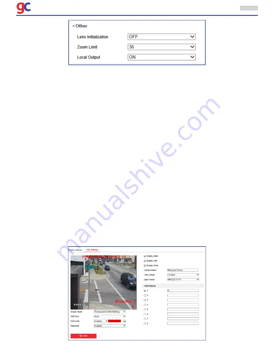
Lens Initialization
The lens operates the movements for initialization when the user checks the check box of
Lens Ini-
tialization.
Zoom Limit
The user can set
Zoom Limit
value to limit the maximum value of zooming. The value can be set to
20, 40, 80, 160 and 320.
Note
: This function varies depending on the models of the ITS Camera.
Local Output
The user can select the output mode to ON or OFF.
3.5.2 Configuring OSD Settings
Purpose:
The ITS Camera supports following on screen displays:
Zoom
: Identifies the amount of magnification.
Direction:
Displays panning and tilting direction, with the format of PXXX TXXX. The XXX
following P indicates the degrees in pan direction, while the XXX following T indicates the degrees in
tilt position.
Time:
Supports for time display.
Preset Title:
Identifies preset being called.
Camera Name:
Identifies the name of ITS Camera.
The user can customize the on screen display of time.
Steps:
• 1. Enter the OSD Settings interface:
Configuration > Image > OSD Settings


