


Commissioning
English, Revision 07, Date: 07.03.2018
57
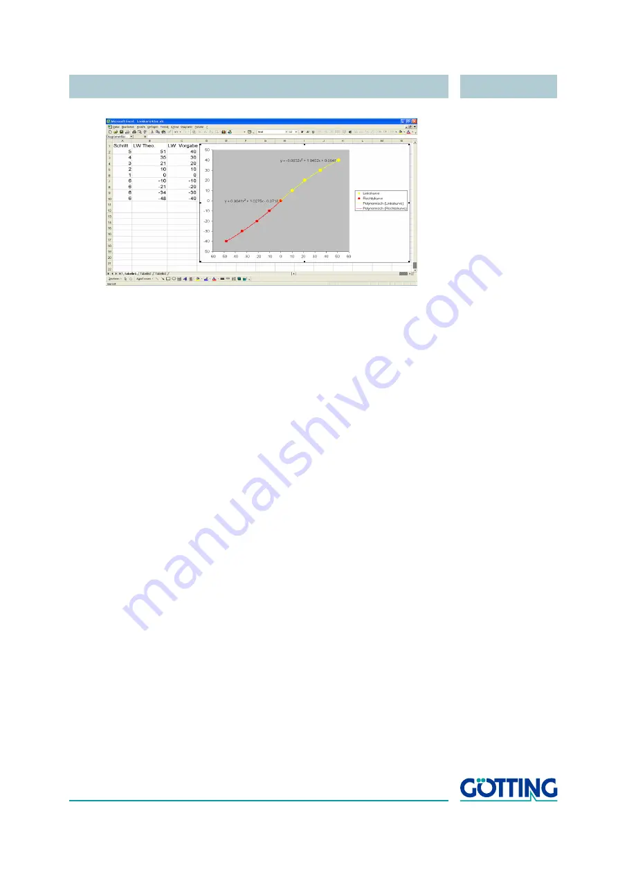
Figure 26
Calculation of the correction coefficients
Column A describes the required steps, column B the theoretical steering angles and
column C the given steering angles.
Comp. Middel
is the average offset of both
equations (see Table 35 on page 56).
4.11.5
(E) Stering Controller
The steering angle controller calculates the steering angle, required to follow the in-
tended track. This controller consists of two parts:
1.
The first part is a feed back controller in the traditional sense. It is possible to
parameterize this angle controller using the parameters A-D, P, PI or PDT1. The
output of the controller can be limited via the parameters G and H. This control-
ler is only used for some vehicles for special tasks.
2.
The second part is the actual feed back controller of the steering controller. Nor-
mally the vehicle is steered by this controller. It works on straight lines only (cor-
nering is achieved via overlaying a curve feed forward control). The controller
always calculates the steering angle to point to a section on the nominal track in
front of the vehicle.
If the steering of the vehicle is directly connected to the steering controller, it is possi-
ble to activate a steering servo. The steering servo is an subordinate controller trig-
gered every 5 ms. It controls the steering motor in such a way that the desired steering
angle will be adjusted (proportional controller).


