


Commissioning
English, Revision 07, Date: 07.03.2018
28
4
Commissioning
For hardware mounting please see our included hardware description for control unit
HG 61430
.
CAUTION!
When starting the commissioning of the vehicle
ensure that all
safety devices are installed and functional
!
NOTE!
At the beginning of commissioning, the vehicle has to be lifted up
from the ground!
If the vehicle has a vehicle control unit (recommended) part of the commissioning
tasks can be fulfilled without the vehicle itself. This primarily affects the communication
between the steering controller and the vehicle control unit.
4.1
Commissioning of Communication
Internal system communication between the components is normally done via CAN
bus. Therefore it is recommended to use a corresponding CAN adapter and a CAN
display program, for example
Peak CAN Bus Adapter
and
PCAN Explorer
.
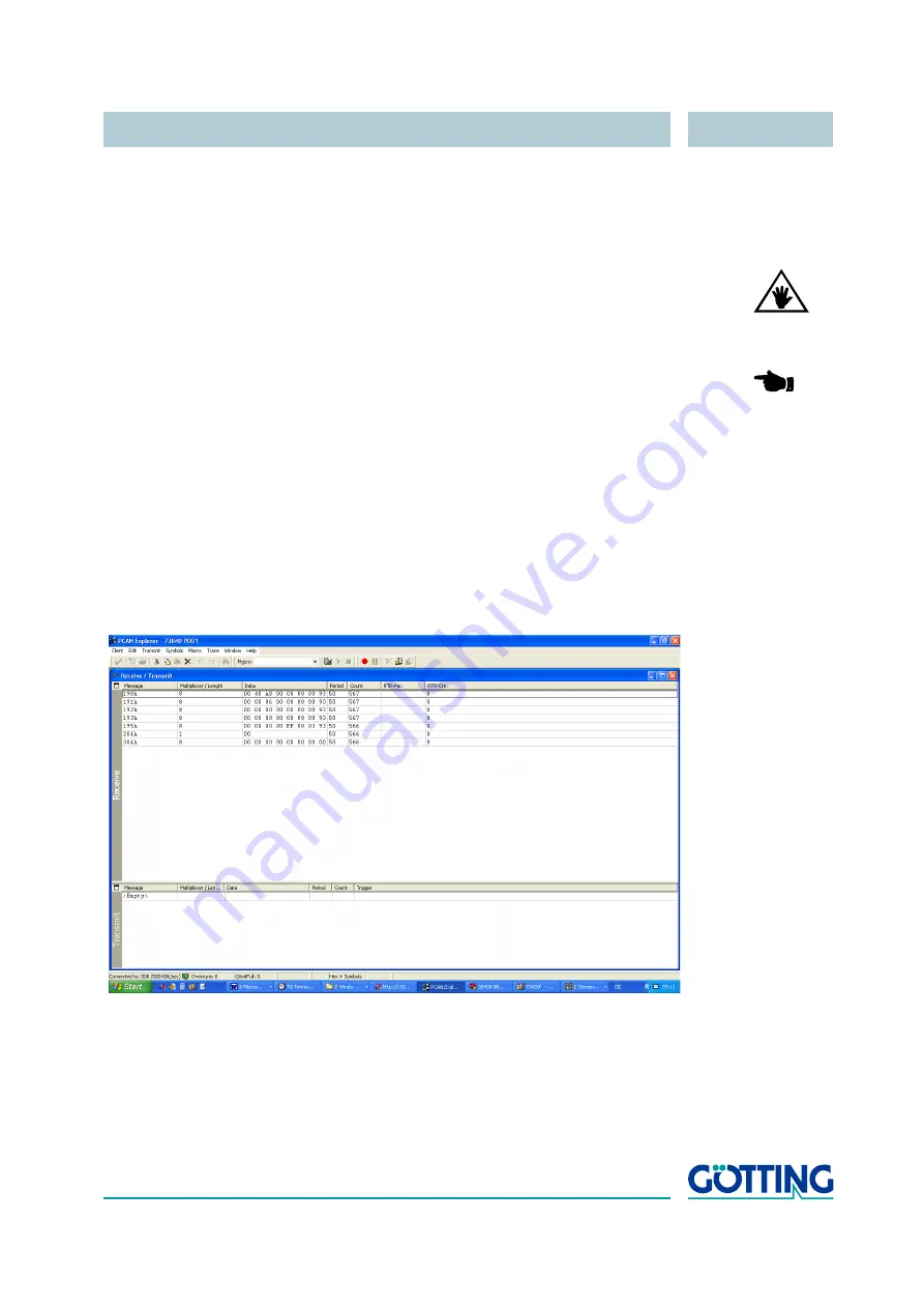
Figure 13
PCAN explorer displaying messages of the steering controller
When switched off the resistance of the CAN bus has to be measured. The CAN bus
must be terminated with 60 ohm all together (either 120 ohm each end of a line network
or 60 ohm centrally of a star network). Only if this can be assured it is possible to start
up the guidance controller and test the basic communication via CAN bus with the
PCAN explorer. Subsequently further commissioning should be implemented using a
PC / laptop and the corresponding terminal program.


