Gossen MetraWatt R2900 Operating Instructions Manual Download Page 9

GOSSEN METRAWATT GMBH

9

EN 55022 requires the following warning as regards electromagnetic compatibility:

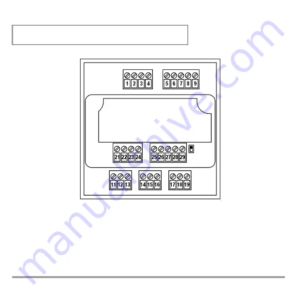
Figure 3, Connector Terminal Positions

Warning

This is a class A device. It may cause radio interference in residential surroundings. If this is the 

case, the operator may be required to implement appropriate corrective measures.

Connectors: 

Screw terminals for wire with a cross section of 1.5 square mm or
two-core wire-end ferrules with a cross-section of 2 x 0.75 square mm

Tighten screws with a manual screwdriver only! Tightening torque for all screw termi-
nals: max. 0.6 Nm

Summary of Contents for R2900

Page 1: ...R2900 Compact Controller 96 x 96 mm 3 349 203 15 3 3 03 Operating Instructions ...

Page 2: ...ontrol 15 Off Manual Operation 16 Manual Operation with Binary Input 17 PWR Out Offset with Binary Input 17 Configuration 18 Saving and Loading Device Settings 21 Differential Controller 21 Slave Controller 21 Controller Sorts 22 Configuration of the Controller with Continuous Output desig A7 and A8 23 Parameters Configuration 24 Balancing 26 Self Tuning 27 Manual Self Tuning 28 Setpoint Ramps 31 ...

Page 3: ...tected with a fuse or circuit breaker with a maximum nominal current rating of 16 A The installation must include a switch or a circuit breaker which serves as a disconnecting device The controller may not be used If visible damage is apparent If it no longer functions flawlessly After lengthy periods of storage under unfavorable conditions e g humidity dust temperature In such cases the device mu...

Page 4: ...hone 49 0 911 8602 410 256 Fax 49 0 911 8602 253 E Mail service gmc instruments com This address is only valid in Germany Please contact our representatives or subsidiaries for service in other countries Product Support When you need support please contact GOSSEN METRAWATT GMBH Product Support Hotline Phone 49 0 911 8602 112 Fax 49 0 911 8602 709 E Mail support gmc instruments com ...

Page 5: ...contr w heat current monit 1 continuous output and 2 transistor outputs Cont action contr step action contr 3 step contr w heat current monit 1 continuous output and 2 relay outputs A1 A2 A3 A4 A5 A6 A7 A8 Measuring Ranges Input Thermocouple configurable Type J L 18 850 C 0 1562 F Type K 18 1200 C 0 2192 F Type S R 18 1770 C 0 3218 F Type B 0 1820 C 32 3308 F especially 600 C Type N 18 1300 C 0 23...

Page 6: ...VDE 0100 must be observed during the performance of all work Work on the device may only be carried out by trained personnel who are familiar with the dan gers involved Set the housing into the panel cutout from the front and secure it from behind at the left and right hand sides with the two included screw clamps Typical tightening torque amounts to 10 Ncm and a value of 20 Ncm should not be exce...

Page 7: ...H 7 Figure 2 Securing the Housing Securing the two screw clamps at the right and left hand sides of the housing Push in direction 1 all the way up to the limit stop Push in direction 2 all the way up to the limit stop 1 2 ...

Page 8: ...A5 A7 I II A1 A3 A5 A7 1 2 3 4 5 6 7 8 9 A3 A4 A6 A8 A2 A4 A6 A8 Switching Output Heating Current Transf A1 A2 A3 A4 A7 A8 11 12 13 14 15 16 17 18 19 B1 B3 B4 B3 A5 A6 Repeater B2 B4 Sensor 1 Sensor 2 21 22 23 24 25 26 27 28 29 D1 A7 A8 C B A F1 10V 20 mA GND TxD RxD Alarms Continuous Output RS 232 RS 485 I II 20 mA 10 V 20 mA 10 V A1 A2 ...

Page 9: ...e radio interference in residential surroundings If this is the case the operator may be required to implement appropriate corrective measures Connectors Screw terminals for wire with a cross section of 1 5 square mm or two core wire end ferrules with a cross section of 2 x 0 75 square mm Tighten screws with a manual screwdriver only Tightening torque for all screw termi nals max 0 6 Nm ...

Page 10: ...e After Activating Auxiliary Voltage U M Software Version Current Configuration LED Segment Test approx 2 s approx 1 5 s CnF1 Actual Value Setpoint or oFF approx 1 5 s Current Configuration B Designation D Designation CnF2 A Designation ...

Page 11: ...rk briefly to indicate activation of the selected value W2 A2 A1 II I R2900 GOSSEN METRAWATT Actual value or Setpoint heating current Setpoint 2 active Off manual operation value or parameter designation Switching output I Switching output II Alarm s active Select off manual automatic operation Shift displays levels and values see operating flow chart Up and down scrolling keys for value selection...

Page 12: ...s and hold both keys until the display is switched page 24 page 18 Only appears when heating current monitoring is activated Setpoint can only be selected here for Extended oper ating level when configured as differential con troller see page 13 fixed setpoint controllers I II A1 A2 W2 Actual Setpoint I II A1 A2 W2 Actual I Heat I II A1 A2 W2 Actual M Factor I II A1 A2 W2 Param Value I II A1 A2 W2...

Page 13: ... key until the display is switched Press and hold both keys until the display is switched page 24 page 18 Only appears when heating current monitoring is activated Differential setpoint can only be selected here I II A1 A2 W2 Diff Set I II A1 A2 W2 I Heat I II A1 A2 W2 M Factor I II A1 A2 W2 Param Value I II A1 A2 W2 Parameter Value I II A1 A2 W2 I II A1 A2 W2 I II A1 A2 W2 Act Val 1 Actual Diff A...

Page 14: ...display is switched Press and hold both keys until the display is switched page 24 page 18 Setpoint can only be selected here for fixed setpoint controllers Extended operating level when configured as differential con troller see page 15 I II A1 A2 W2 Act Val Setpoint I II A1 A2 W2 Act Val M Factor I II A1 A2 W2 Param Value I II A1 A2 W2 Param Value I II A1 A2 W2 I II A1 A2 W2 Only for step action...

Page 15: ...key briefly Press and hold key until the display is switched Press and hold both keys until the display is switched page 24 page 18 Differential setpoint can only be selected here I II A1 A2 W2 Diff Set I II A1 A2 W2 I II A1 A2 W2 Actual Diff M Factor I II A1 A2 W2 Param Value I II A1 A2 W2 Param Value I II A1 A2 W2 I II A1 A2 W2 Only for step action controllers with designation A5 A6 Actual Diff ...

Page 16: ...played in Values are changed with the and keys and are forwarded immediately to the control outputs Step action controller Switching output I more or II less is triggered directly by pressing the or key If posi tion acknowledgement is utilized designations A5 and A6 the measured position is displayed as a percentage and bars are displayed for all other designations No alarm function No indication ...

Page 17: ...0 The alarm 2 configuration digit must be set to a value of 8 F to this end see also CnF2 on page 20 PWR Out Offset with Binary Input When configured as a step action or a continuous action controller controller sort set to 2 through 5 control quality can be significantly improved by means of PWR out offset where abrupt load fluctuations prevail When the contact at the binary input is closed the c...

Page 18: ... heat Relative Active 2 step controller cooling Absolute 3 step controller Relative Inactive NC contact 3 step controller water cooling Absolute Step action controller Relative Active Absolute Relative Inactive NO contact Active Absolute Relative Active Absolute Relative Inactive NC contact Absolute Relative Active Absolute Gray highlighting default setting K0 Settings for continuous action contro...

Page 19: ...C 4 20 mA 2 10 V K F B C 0 20 mA 0 10 V Manipulating factor cont action controller S F R C 4 20 mA 2 10 V N F 1 Display Pt 100 C 0 20 mA 0 10 V Select output quantity with Cont see also page 23 0 1 Display F 0 20 mA 0 10 V Std signal For measurement input 1 with designation B2 C 4 20 mA 2 10 V 4 20 mA 2 10 V F no function Saving and loading device settings see page 21 1 Switching to and from C and...

Page 20: ...t Setpoint 2 delete Differential Fixed setpoint Absolute Slave controller Relative Active Absolute Fixed setpoint controller 4 20 mA 2 10 V Relative Inactive NC contact Absolute Slave controller Relative Active Absolute Relative Inactive NO contact Manual automatic or PWR out off set Absolute Relative Active Absolute Relative Inactive NC contact Absolute Relative Active Absolute Gray highlighting ...

Page 21: ...er becomes a fixed setpoint controller using set point 2 SP2 Upper and lower limits for the external setpoint are scaled with the rnL and rnH parameters 2nd measurement input standard signal for designation B4 The SPL and SPH parameters limit the external setpoint for control and display purposes If an attempt is made at the operating level to change the setpoint display mode actual value setpoint...

Page 22: ...alue The actuating cycle is equal to at least tc 2 step controller cooling 3 step controller A harmonic free PDPI control algorithm regulates switching output I in order to increase the actual value or switching output II in order to decrease the actual value The actuating cycle is equal to at least tc The dead band dbnd suppresses switching back and forth between heating and cooling if no lasting...

Page 23: ...nic free PDPI control algorithm regulates the continuous output every 0 5 seconds An output filter assures smoothest possible actuating signal char acteristics tc is used to set the time constant for an additional actual value filter Continuous controller with rising char acteristic curve Split range controller Continuous controller with falling characteristic curve for positive manipulating facto...

Page 24: ...d heating 0 1 999 9 10 0 Proportional band cooling 0 1 999 9 10 0 Only with 3 step controllers 2 Dead band 0 MR 0 Not with 2 step controllers 3 Path delay time 0 9999 s 100 Read out cycle time 0 5 600 0 s 10 0 4 Motor run time 5 5000 s 60 Only with step action control lers 5 Switching hysteresis 0 1 5 MR 0 5 MR For limit value monitoring and limit transducers Maximum setpoint SPL X2 X2 Minimum set...

Page 25: ...manipulating factor 100 100 0 Continuous signal See page 23 0 Only for designations A7 and A8 Interface address 0 250 250 Only with designation F1 1 Only where controller sort configuration digit 6 and designation A5 A6 2 Only where controller sort configuration digit 4 or 5 3 Only where controller sort configuration digit 0 4 5 or 6 4 Additional actual value filter for continuous action controlle...

Page 26: ...uiring heating current the current value must be selected at which the utilized transformer generates an output volt age of 10 V DC Calibrating the Position Acknowledgement Display parameter Y100 Y 0 Calibration is performed in the manual operating mode at the parameter level with the device configured as a step action controller controller sort configuration digit 6 1 Select parameter Y 100 The s...

Page 27: ...etermined Read out cycle time tc is not changed during self tuning We recommend for tc a value of tu 12to guarantee satisfactory controller dynamics When controlling contactors tc should be adequately increased Preparation Complete configuration must be performed before self tuning is started The setpoint value is adjusted to the value which is required after self tuning Start Briefly press the ke...

Page 28: ...rder channel or a stopwatch Configure as limit transducer controller sort 0 Set read out cycle time to the minimum value tc 0 5 If possible deactivate manipulating factor limiting YH 100 Reduce or increase the setpoint so that overshooting and undershooting do not cause any impermissible values Performing the Actuation Test dbnd MR Setting for 3 step and split range controllers switching output II...

Page 29: ...ors tc should be adequately increased If manipulating factor limiting was active the proportional band must be corrected YH positive Pb 1 multiply by 100 YH YH negative Pb1 1 multiply by 100 YH Parameter Values Parameter 2 step controller 3 step controller Continuous action controller Split range controller Step action controller tu 1 5 t t tY 4 tc tu 12 1 tY 100 Pb 1 xss MR 100 xss MR 200 x MR 50...

Page 30: ...ge and step action controllers Activate the actuators with automatic operation and start the recorder if applicable Record several oscilla tions until they become uniform in size Measure oscillation amplitude xss Record on time TI and off time TII at switching output I or the continuous output for the oscillations Evaluating the Oscillation Test 1 If either TI or TII is significantly greater than ...

Page 31: ...rom dbnd 0 for 3 step split range and step action controllers if con trol of switching output I or the continuous output and II changes too rapidly for example due to an unsteady actual value Setpoint Ramps Function Parameters SPuP and SPdn cause a gradual temperature change rising falling in degrees per minute Activation When auxiliary power is switched on When the current setpoint is changed Whe...

Page 32: ...witched on The measured current value is saved to memory Heating Circuit Monitoring Function Can be set to active or inactive with the alarm configuration digit see Configuration Without external transformer without additional parameters Assumes correct optimization of tu and Pb 1 control parameters i e heating circuit monitoring must be activated before self tuning is started In the event of manu...

Page 33: ...lue selection has been completed during configuration or parameter setting Alarm Relay n NO Contact Alarm Relay n NC Contact n 1 2 ALnL ALnH Relative Limit Values ALnL ALnH Absolute Limit Values Blinking Display at operating level only Error Message Source Display Response Comment Heating current Heating current monitoring LED A1 blinks Alarm output A1 and LED A1 are activated 1 1 Only for designa...

Page 34: ...lection has been completed during configuration or parameter setting 4 Exceptions and additional information are included in the following table Display Error Message Source Response Remedy sensor error high Broken sensor or actual value greater than up per range limit 1 sensor error low Sensor polarity reversed or actual value less than lower range limit current error Current transformer has reve...

Page 35: ...settings 7 Arrange for repair at authorized service center tune error 2 Disturbance in self tuning sequence in steps 1 through 13 step 2 in this case Control outputs I and II inactive Self tuning must be aborted 4 loop error Measured temperature rise is too small with heat on at 100 Control outputs I and II inactive Error message is not cleared until key is pressed and held 5 parameter error Param...

Page 36: ...48 Hz 62 Hz Max 10 VA typically 6 W Relay Output Floating normally open contact Switching capacity AC DC 250 V 2 A 500 VA 50 W Service life 2 105 switching cycles at nominal load Interference suppression Utilize external RC element 100 Ω 47 nF at contactor Transistor output suitable for commercially available semiconductor relays SSR Switching Status Open Circuit Voltage Output Current Active load...

Reviews: