
78
GMC-I Gossen-Metrawatt GmbH
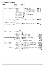
Significance of Register Contents
n
= decimal equivalent of register content (0
≤
n
≤
255).
Condition Register
(
→
page 64)
Condition Register A (CRA)
The individual bits of the condition register reflect the momentary
status of a specific device function:
0 = condition does not apply (FALSE)
1 = condition applies (TRUE)
The content of the condition register can be read out, but direct
overwriting and deletion are not possible.
Event Registers
(
→
Standard event register (ESR)
Event register A (ERA)
Event register B (ERB)
The event registers acquires and save status changes which have
occurred for specific device functions. The corresponding bit is
set to 1 in the event register (1 = TRUE), when the respective
function status
– is changed from FALSE to TRUE (for input
) or
– from FALSE to TRUE (for input
).
The three event registers can be individually queried. When an
event register is queried, its content is deleted. Setting command
*CLS
clears all event registers.
An enable register is assigned to each event register.
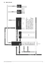
Enable registers
(
→
Standard event enable register (ESE)
Event enable register A (ERAE)
Event enable register B (ERBE)
Service request enable register (SRE)
Parallel poll enable register (PRE)
The enable registers determine which bit(s) from the
corresponding event or status byte register is/are capable of
influencing the respective group message. The respective group
message remains set (1 = TRUE), as long as at least one bit
which has been enabled to this end has a status of TRUE.
The five enable registers can be written to and read separately.
Queries, the *CLS command and device functions do not cause
any changes to the contents of these registers. The registers can
be cleared by entering a value of “0” (e.g. *
ESE 0
). Exception:
The enable registers are non-volatile, and are only cleared by
means of device shutdown if the non-volatile PSC flag is set to 1.
Status Byte Register (STB)
(
→
The status byte register contains:
– The status of group messages from the three event registers
(bits 2, 3 and 5)
– The status of the output buffer (empty —> MAV (bit 4) = 0, not
empty —> MAV = 1)
– The status of MSS group messages masked with the SRE
enable register from internal bits 2, 3, 4 and 5 (bit 6).
– Bits 0, 1 and 7 are not used, and are always set to “0”.
Register content can be read out:
– With the *STB? command, or
– With the “serial poll” interface command in the event of IEC bus
operation. If this is the case, bit 6 indicates the RQS status,
which is reset (0) after completion of serial polling.
The *CLS command clears the status byte register except for the
MAV bit, and cancels any SRQ messages.
Power-On Status Clear Flag (PSC)
(
→
The power-on status clear flag determines whether or not the
contents of the non-volatile enable registers, ESE, SRE and PRE,
will be cleared when the device is shut down.
The PSC flag can be set and queried:
Set:
*PSC
n n
= 0: ESE, SRE and PRE are not cleared
n
= 1: ESE, SRE and PRE are cleared
Query:
*PSC?
response: “0” or “1”
The PSC flag setting is retained, even after the device has been
switched off.
Operation Complete Flag (OPC)
(
→
A ready message can be triggered with the operation complete
flag after one or several transmitted commands have been
executed by the device.
The OPC bit is set in the standard event register by means of the
*OPC
command, because it is not processed until after all
previous commands have been executed.
The response to query command
*OPC?
is always “1”, because it
is not processed until all previous commands have been
executed.
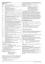
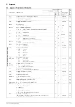
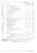
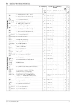
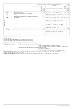
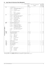
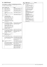
Register
Name
Meaning
CCR
Output is/was in current regulating mode
CVR
Output is/was in voltage regulating mode
CME
Unrecognized command, syntax error, standard limit values for numeric
parameters exceeded
DDTE
Define device trigger function error message:
– *DDT command string > 80 characters or
– *TRG command included in *DDT command string
EXE
Command-specific parameter limits exceeded, a command or parameter is
incompatible with present operating state
LIME
Error message after setting command USET, ISET, ULIM, ILIM: An attempt
has been made
– to select a voltage or current setpoint which is higher than the defined limit
value, or
– to select a limit value which is lower than the momentary voltage or current
setpoint.
MAV
Error message following a query command: The requested information is
available at the output buffer. The MAV bit should only be queried by means
of serial polling during IEC bus mode operation.
OCPA
Output deactivated by OCP function. Reactivate with OUTPUT ON.
OL
Overload message: Power limiting has been triggered.
OPC
Ready message: Commands preceding the *OPC command have been
executed (time synchronization).
OTPA
Overtemperature message: The device is overheated, e.g. due to obstructed
vents. The output is deactivated 5 seconds after this message appears. The
OUTPUT ON setting command is ignored as long as this condition persists,
and causes repeated setting of the OTPA bit in the event register.
OTPI
Ready for operation message after OTPA overtemperature message: The
device has cooled back down. If the POWER ON function is set to standby or
reset, the output remains deactivated. If the POWER ON function is set to
recall, the output is automatically reactivated.
OUTE
Error message after OUTPUT ON command: Activation of the output is
disabled by an OUTPUT OFF signal at the trigger input of the analog interface.
Display: “Err 25”
OVPA
Overvoltage protection has been triggered and the output has been
deactivated. Reactivate with OUTPUT ON.
TPE
Error message: Error or mains phase failure detected during self-test (only for
devices with 3-phase mains connection)
PON
The device was switched off for an interim period of time.
QYE
Error message after addressing as talker: No message is (yet) available at the
output buffer.
SEQB
Status message: Sequence function active (run, hold)
SEQI
Ready message: The SEQUENCE has been completed, or was aborted
(inactive, ready).
SEQE
Error message after SEQUENCE GO:
– A voltage or current setpoint value which has been recalled from
SEQUENCE memory is higher than the respective limit value (USET > ULIM or
ISET > ILIM). Display: “Err 21” or
– No executable values exist within the storage area defined by the START
and STOP addresses. Display: “Err 22”
The SEQUENCE is aborted after the error message appears.
TRGA
Trigger at analog interface:
Trigger signal detected at analog interface.