
GMC-I Gossen-Metrawatt GmbH
69
Comment
The setting status of the OCP function is indicated by the yellow
“OCP ON” LED at the front panel.
Deactivation of the power output initiated by the OCP function is
indicated by the red “OCP” LED at the front panel, and bit 3 is
simultaneously set in event register A (OCPA, overcurrent
protection activated).
After OCP shutdown has occurred, the output is reactivated with
OUTPUT ON.
If the OCP function has been activated and ISET and DELAY have
been set to low values, the output may even be deactivated if
output voltage is increased. This is due to the fact that charging
current for the output capacitor is also acquired by the current
regulator, and is limited to a value of Iset – Iload. For this reason,
DELAY must be set to a value higher than the resulting output
voltage response time.
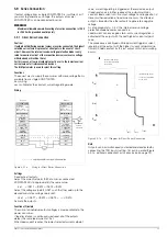
OUTPUT, OUTPUT? – Activate / Deactivate the Output
Functions
The power output can be activated and deactivated with the
OUTPUT function.
Activation sequence:
Current and voltage values of “0” are specified
initially for a period of approximately 2 ms with activated output
for transition from the “highly resistive” condition. The output is
then adjusted to the selected voltage and current setpoints.
Deactivation sequence:
Current and voltage setpoints are set to 0 V
and 0 A for a period of approximately 350 ms (500 ms for 80 V
nominal voltage). The sink is thus activated. The sink discharges
the output capacitors as far as possible. The sink is then
deactivated so that the output becomes highly resistive for
parallel connected direct voltage sources of less than nominal
voltage. However, the output terminals are not electrically
enabled.
Syntax
OUTPUT
status
Parameter
Status
The desired
status
can be selected with one of the
following text parameters:
OFF
Deactivate the output.
ON
Activate the output.
Default setting after RESET (*RST):
OFF
a) Manual Operation
The power output can be switched on and off by activating the
<OUTPUT> key.
b) Programming
Setting
Setting command:
OU
TPUT
status
Example (HP Basic):
OUTPUT 712;"OUT ON"
!Activate output
Setting query
Query command:
OU
TPUT
?
Response string:
OUTPUT
status
Possible response parameters for (
status
):
"
OFF
"
output deactivated
"
ON
"
output activated
Fixed response string length: 10 characters
OUTPUT 712;"OUTPUT?"
ENTER 712;A$
DISP A$
→
Display:
OUTPUT ON
Comment
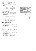
The setting status of the OUTPUT function is indicated by the red
“OUTPUT” LED at the front panel.
LED on
= output activated
LED off
= output deactivated
The control mode displays are inactive when the status is set to
OUTPUT OFF.
If an attempt is made to activate an output which has been
disabled by an external trigger signal to the analog interface in the
T_MODE OUT operating mode by means of a command or a key
operation, the setting command is not executed and bit 4 is set in
event register B (output-on error). “Err 25” also appears briefly at
the display as a warning in the event of manual operation.
Additional functions which may influence the status of the output
include:
– OTP, overtemperature protection (
→
– OVP, overvoltage protection (
→
– OCP in the event of "OCP ON" (
→
– SEQUENCE function (
→
– T_MODE function (
→
– POWER_ON (
→
OVSET, OVSET? – Overvoltage Protection Trigger Value
Functions
OVSET is used to define the trigger value (threshold) for the
overvoltage protection function. If voltage at the output terminals
exceeds the selected value, the power output is deactivated.
Syntax
OVSET
value
Parameter
Value
Parameter type:
real number
a) Manual Operation
b) Programming
Set
Setting command:
OVS
ET
value
Example (HP Basic):
OUTPUT 712;"OVSET 35.0"
!Overvoltage protection trigger value: 35 V
Setting query
Query command:
OVS
ET
?
Response string:
OVSET
value
Parameter format
value
:
+nnn.n
Fixed response string length: 12 characters
Example (HP Basic):
OUTPUT 712;"OVS?"
ENTER 712;A$
DISP A$
→
Display:
OVSET +035.0
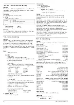
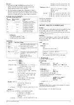
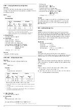
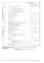
Comment
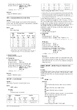
Overvoltage protection can be triggered by:
Device Type
Setting Range
Step Size
Nom.
Voltage [V]
Min.
[V]
Max.
[V]
Remote
a)
[V]
a. If the selected
value
is not a whole number multiple of the step size, it is
rounded off accordingly. If necessary, the numeric value is rounded off once
again for the 4-place digital display.
Manual
b)
[V]
b. Can be selected by (repeatedly) pressing the <RESOLUTION> key. The
blinking decimal place at the display indicates the selected step size.
40
3.00
50.00
0.1
0.1 / 1.0
52
3.00
62.50
0.1
0.1 / 1.0
80
3.00
100.00
0.1
0.1 / 1.0
Default setting after RESET (*RST): Maximum