OM-06114
VGH SERIES
MAINTENANCE & REPAIR
PAGE E - 7
race, rollers, balls, or ball cage. Press
only
on the inner race.
If heating the bearings is not practical, use a suit
ably sized sleeve and an arbor (or hydraulic) press
to install the bearings on the shaft.
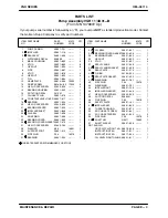
Install the outboard bearing spacer (21). Installthe
snap ring (24) in the groove in the impeller shaft.
Position the bearing housing on a secure work sur
face with the drive end facing up. Slide the shaft
into the bearing housing
until the bearing (19)
seats against the bearing bore shoulder.
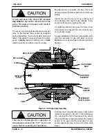
Press the oil seal (23) into the bearing cover (25)
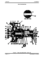
with the lip positioned as shown in Figure 1. Install
the gasket (26) and secure the bearing cover to the
bearing housing (15) with the capscrews (20).
Position the bearing housing on a secure work sur
face with the seal plate end facing up. Press the
outer ring and rollers of the inboard bearing (31)
into the bearing housing until fully seated.
Install the inboard oil seal (32) in the bearing cover
(34) with the lip positioned as shown in Figure 1.
Slide the inboard bearing cover and gasket (33)
over the shaft and secure them with the capscrews
(14).
Secure the foot (29) to the bearing housing with the
hardware (27 and 28). Support the bearing hous
ing with a wood block until the pump is fully reas
sembled. Lubricate the bearings as indicated in
LUBRICATION
at the end of this section.
Wear Ring Installation
Inspect the throat bushing (52) for wear or scoring.
If replacement is required, position the seal plate
on the bed of an arbor (or hydraulic) press with the
impeller end facing up and use a suitably sized
dowel to press the bushing from the seal plate
bore.
Invert the seal plate on the press and use a suitably
sized sleeve to install a new bushing in the seal
plate.
The throat bushing
must
seat squarely in
the seal plate bore; otherwise binding and/
or excessive wear will result.
If the wear rings (42 and 44) were removed for re
placement, press the replacement rings into the
pump casing and seal plate until they seat squarely
against the shoulders.
The wear rings
must
seat squarely in the
casing and seal plate bores; otherwise
binding and/or excessive wear will result.
The seal plate wear ring is held in place with an M5
x 10mm setscrew (53). With the wear ring installed
in the seal plate, drill a 4 mm diameter by 12mm
deep hole between the O.D. of the wear ring and
the I.D. of the seal plate. Tap the hole with an M5
tap, and secure the wear ring by installing the set
screw (53).
NOTE
3/16-24 x 3/8 SAE setscrews may be substituted
for the M6 x 6mm metric setscrews. Drill and tap the
holes accordingly if using SAE setscrews.
Seal Installation
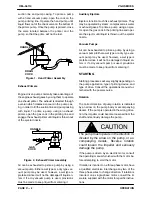
(Figures 1 and 2)
Clean the seal cavity and shaft with a cloth soaked
in fresh cleaning solvent.
Most cleaning solvents are toxic and
flammable. Use them only in a well ven
tilated area free from excessive heat,
sparks, and flame. Read and follow all
precautions printed on solvent contain
ers.
Inspect the shaft for damage. Small scratches or
nicks may be removed with a fine file or emery
cloth. If excessive wear exists, replace the shaft.

