


GHS SERIES
OM-05450
PAGE E-5
MAINTENANCE AND REPAIR
pumps are equipped with drain plugs in the head
and backhead. Remove the plug(s) and drain the
pump before proceeding with disassembly.
Pressure Relief Valve (10)
If the pump is equipped with a pressure relief valve
(10A), it can be mounted on either the head assem
bly (01A) or the housing assembly (04). Some
models are equipped with one of each. Take note
as to the direction in which the relief valve is
mounted. To remove either style, remove the caps
crews (B) securing the relief valve to the pump. The
O‐rings (10C) may remain in the head (01A) or in
the housing (04A). Remove and discard the O‐
rings. For relief valve maintenance, see
RELIEF
VALVE DISASSEMBLY
followed by
RELIEF
VALVE REASSEMBLY
at the end of this section.
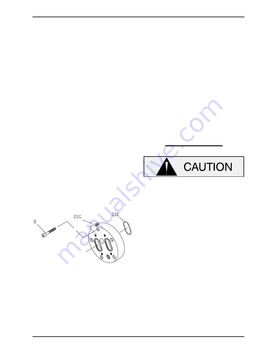
Optional Head Jacket
(Figure E‐1 And E‐2)
If your pump is equipped with an optional head
jacket, see Figure E‐2 and remove the capscrews
(B) securing the head jacket (01G) and O‐rings
(01E) to the head assembly (01A, Figure E‐1).
Figure E‐2. Typical Head Jacket Assembly
Rotor Adjusting Sleeve (07)
Before attempting to remove the bearing locknut
(03C), loosen the socket head setscrews (GA) se
curing the rotor adjusting sleeve (07) and use a
pipe wrench or other suitable tool to turn the rotor
adjusting sleeve clockwise (as viewed from the
drive end) until the rotor binds against the head.
This will prevent the rotor from turning as the lock
nut is unscrewed.
Straighten the tab on the bearing lockwasher (03B)
and use a hammer and drift pin to loosen the bear
ing locknut until it can be unscrewed from the
shaft. Remove the bearing lockwasher.
Unscrew the rotor adjusting sleeve kit from the
backhead.
NOTE
Part or all of the seal assembly (05) may be re
moved with the rotor adjusting sleeve. Check the
Parts List
furnished with your pump to identify the
seal, refer to
Seal Appendix
,
Section F
, for removal
of the seal and related components, then proceed
as follows with rotor adjusting sleeve disassembly.
When removing or installing the bearing
(07AC), never hit or press against the inner
race. Press
only
against the outer race.
Secure the rotor adjusting sleeve (07AA) in a vice
with the drive side down. Position a suitably sized
screwdriver horizontally through the slots in the
bearing retaining nut and use the screwdriver to
unscrew the bearing retaining nut from the rotor
adjusting sleeve. The bearing (07AC) is a light
press fit into the rotor adjusting sleeve and can
usually be removed with thumb pressure only. If
the bearing does not come out easily, use a suit
able sized sleeve and a mallet to lightly tap the
bearing from the bore.
Refer to
Cleaning and Inspection
in this section
before reassembling the rotor adjusting sleeve.
Coverplate Kit (11)
(Figure E‐1 And E‐3)
The coverplate kit may be mounted on either the
head assembly or the housing assembly. Removal
is the same for either.


