GORBEL TETHER TRACK TTSA Installation, Operation & Maintenance Manual Download Page 18

STEP 10 - ROTATION STOP INSTALLATION (OPTIONAL)

10.1

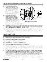
  When ordered with a rotation stop,


one bracket will have a plate welded


to it with slots to accept rotation stop


bolts. This bracket must be installed


as the upper bracket. Additionally, an


angle with mounting hardware is


included to be installed on the vertical


member of the Swing Arm. Refer to


diagram 10A

 for the following steps.

10.2

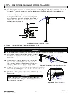
  Follow Swing Arm installation


instructions in Step 2 on page 7 or


Step 4 on page 10. When tightening


the top pivot bolt, use the included


insert as a socket to hold the nut while


tightening the bolt (a deep socket or


other method may be used at the


installer’s discretion). Once the bolt is


tight, the insert may be removed but


should be kept in the event the bolt ever needs to be removed.

10.3

  Install the rotation stop studs and nuts in the stop plate but do not fully tighten yet. Install the stop angle with


included hardware and adjust vertically so the bottom of the angle is even with the top of the flange on the


stop nut (

diagram 10A

). Torque hardware per 

chart


8A

, page 14.

10.4

  Locate rotation stop hardware in the stop plate such that when the nut hits the stop angle, the Swing Arm is


prevented from hitting any obstruction and that the fall zone is away from any dangerous machinery or


conditions. Orient the nuts so the flat of the hex contacts the flat of the stop angle. Torque stop hardware

  per 

chart 8A

, page 14.

STEP 11 - FINAL STEPS

11.1

  Check to make sure all bolts are tight and lockwashers are compressed.

11.2

  Grease all fittings (use Lubriplate #630-AA or equivalent).

11.3

  If necessary, touch up system with paint provided.

11.4

  Install yellow rubber tracdoms on open ends of steel track.

11.5

  Verify capacity labels are legible from the ground or egress location.

11.6

  For more than a one worker system, verify that the required brake or drive is installed and verify that only a


SRL with sufficient extra payout is being used. Additional line is required to allow the Swing Arm to move


during a fall event without the SRL reaching its maximum length which may cause the second worker to lose


his or her balance.

11.7

  Proof testing may be performed if required by state or local jurisdictions. The qualified person responsible


for this fall arrest system may also request a proof load test. The Swing Arm Anchorage System has been


designed to withstand a static proof load test not to exceed 125% of the rated MAAF with no visible


permanent deformation. The trolley shall be slowly loaded to avoid additional dynamic loads. The proof load


should be applied for a minimum of one minute. After this test is complete, the Swing Arm Anchorage


System shall be inspected as if a fall event had occurred.

11.8

  Keep Packing List, Installation Manual, General Arrangement Drawing, and any other inserts filed together


in a safe place.

A

ROTATION

STOP HARDWARE

(STUD AND NUTS)

(ONLY ONE SHOWN)

HEX INSERT

STOP ANGLE

STOP PLATE

PIVOT BOLT

STOP ANGLE

HARDWARE

B

ALIGN STOP ANGLE

WITH ROTATION STOP NUT

Diagram 10A.


Rotation stop installation.

16

10/12 Rev. E


TIP: 

 Do not throw away this manual: the maintenance schedule is on the back cover.

Summary of Contents for TETHER TRACK TTSA

Page 1: ...ntenance Manual Month Year Gorbel Dealer Date Tether Track Swing Arm Systems Gorbel Customer Order No Serial No TTSA FS TTSA Distributed by Engineered Fall Protection Sales EngineeredFallProtection co...

Page 2: ...tion 10 Step 5 Tether Track Installation 10 Step 6 Trolley Installation 11 Step 7 Friction Brake Installation Optional 11 13 Step 8 Drive Installation Optional 14 Step 9 Electrification Installation O...

Page 3: ...rolley within our enclosed track all mounted on a freely pivoting hinge allows for the maximum ease of movement These proven designs have been utilized in Gorbel s crane products for many years Refer...

Page 4: ...ximum average arresting force and the rated maximum arresting force of the Tether Track Swing Arm Anchor System shall not be exceeded If the lanyard or SRL connected to the Tether Track Swing Arm does...

Page 5: ...zed or an engaged friction brake is required when more than one person is using the Swing Arm 11 Only SRLs with sufficient reserve line shall be used when more than one person is using the Swing Arm D...

Page 6: ...1 2 FOR B1 6 7 3 3 1 2 11 16 HOLE FOR 5 8 BOLT 5 4 13 16 HOLE FOR 3 4 BOLT 8 8 1 4 B1 BRACKET B2 BRACKET PULL THRUST Diagram 1A Wall Mounted Swing Arm MAST DIA SPAN TS WIDTH DEPTH Diagram 1B Free Stan...

Page 7: ...B1 1P 30 18 8 625 12 75 12 75 12 75 12 75 14 14 14 14 16 16 18 6 48 48 48 48 48 48 48 48 48 48 48 6 3 4 4 25 4 5 4 5 4 75 5 5 25 5 5 5 75 6 25 6 25 776 1038 1161 1206 1268 1905 1982 2150 2237 2676 324...

Page 8: ...TSA FS WC B2 2P 30 18 12 75 12 75 14 14 14 14 14 16 16 18 18 20 48 48 48 48 48 48 48 48 48 48 48 48 4 5 4 75 5 5 5 5 75 6 6 25 6 5 6 75 7 7 25 7 5 1108 1179 1733 1887 2065 2134 2352 3083 3189 3566 367...

Page 9: ...sembly to formed channel using hardware provided diagram 2B Be sure that thrust washers are in position Tighten nuts on pivot bolt until lockwashers are compressed being sure boom freely rotates 2 5 C...

Page 10: ...concrete must cure seven 7 days prior to mast installation Foundation concrete must cure 28 days prior to using Swing Arm C Proceed to Step 3 2 page 9 for mast installation and plumbing STOP Do not p...

Page 11: ...ude above base plate If base plate hole diameter is greater than bolt diameter plus 1 4 refer to AISC Design Guide 1 for minimum washer size and thickness recommendations C Install anchor bolts and ha...

Page 12: ...n on clamping bolts two at each track support Thread clamping bolts with jam nuts into track supports and tighten until snug against track Lock clamping bolt into place with jam nut diagram 5A 5 3 Ins...

Page 13: ...ON BRAKE INSTALLATION OPTIONAL Brake Caliper Installation 7 1 If brake caliper lever is not assembled in orientation show diagram 7A remove cotter pin adjuster nut flat washer lever mounting bolts and...

Page 14: ...agram 7E 7 6 Slide rotor between brake pads as shown in diagram 7F Loosen 1 2 caliper bracket mounting bolts and position caliper so that rotor overlaps brake pads by 1 16 Tighten 1 2 bolts to 50 ft l...

Page 15: ...16 18 1 5 long hex bolt and lock nut to attach lever weldment to the brake release bracket Attach pull chains to the lever weldment using hardware show in diagram 7J 7 9 Use turnbuckle to adjust cabl...

Page 16: ...t 8A for proper torque rating Friction Clutch Installation During normal operation adjustment to compensate for friction lining wear may be necessary The frequency of these adjustments will be depende...

Page 17: ...d voltage of motor 9 8 Reference drawing E and E 1 for pendant and enclosure schematics when required 9 9 Attach limit switch tab to bottom of vertical member of Swing Arm diagram 9C so that is does n...

Page 18: ...ll bolts are tight and lockwashers are compressed 11 2 Grease all fittings use Lubriplate 630 AA or equivalent 11 3 If necessary touch up system with paint provided 11 4 Install yellow rubber tracdoms...

Page 19: ...le must be the minimum SRL length above the workers dorsal ring Minimum TS WS WH 1 ft SL 10 6 1 2 17 ft Here 1 ft is taken as the distance from the dorsal ring to the worker s full height The trolley...

Page 20: ...event of a fall the Swing Arm may move to vertically align the activated lifeline and may rotate up to an additional 10 degrees To reduce the potential of a second worker from falling extra payout li...

Page 21: ...force rating of the connected lanyard or SRL Note the static proof test load must be based on the maximum average arresting force rating of the Swing Arm multiplied by the maximum number of workers Ea...

Page 22: ...plication of force through the lanyard locked SRL or a tagline will begin to rotate the Swing Arm Allow the Swing Arm to continue to rotate until it is near the overhead position and then gently apply...

Page 23: ...5 Do not exceed the rated load capacity number of workers or maximum average arresting force of the Swing Arm Tether Track Anchor System Labels with this information are located on either side of the...

Page 24: ...pressly excluded E DEALER OR DISTRIBUTOR NOT AN AGENT Gorbel and Purchaser agree that Purchaser has been put on notice that dealer or distributor is not Gorbel s agent in any respect for any reason Go...

Page 25: ...by their manufacturers If the answer to any of these questions on the checklist is no remove yourself from the fall hazard and report the issue to the proper supervisor 23 10 12 Rev E YES NO AUTHORIZ...

Page 26: ...ck pivot points for being out of plumb and shim as necessary For drive option verify normal operation Check clutch slippage by applying a horizontal 40 pound force at the end of the Swing Arm Tighten...

Page 27: ...measuring device ruler tape measure etc measure from support to support covering track area where arrest took place Clamp one end of string to the concave face of track at the support Travel to the o...

Page 28: ...nut for wear Check that clamp plate lockwashers are compressed Check that black spring washer is not deformed and is in place Confirm spring pin is in place Check for smooth rolling action Recover Tro...

Reviews: