


INSTALLATION PARAMETERS AND APPLIED FORCES TO THE
SUPPORTING STRUCTURE
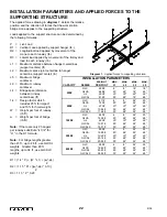
The applied forces drawing in
diagram 1
, details the relative
position and the direction of forces that the work station
bridge crane applies to the supporting structure.
Loads applied to the support structure can be determined by
the following formulas:
P
=
Live Load
R1 =
Vertical Load applied by support hanger (lb.)
R2 =
Longitudinal load applied by movement of the
crane to each runway (lb.)
R3 =
Lateral load applied by movement of the trolley and
load to each runway (lb.)
L1 =
Maximum distance between hanger centerlines
(support centers) (ft)
L2 =
Maximum splice joint centerline to hanger
centerline (support center) (in)
L5 =
Maximum bridge
cantilever
L9 =
Maximum runway
cantilever
L4 =
Bridge span (distance
between runway
centerlines) (ft)
1.4 =
Design factor which
includes 25% for impact
and 15% for hoist weight
W =
Weight per foot of runway
(lb./ft)
w
=
Weight per foot of bridge
(lb./ft)
Note:
If there are only 2 hangers
per runway substitute “(L1)/2” for
“L1” in the R1 formula.
Note:
For bridge lengths greater
than 23 ft., up to 28 ft., use GLCSL
weights. Greater than 28 ft.
lengths, up to 34 ft., use GLCSLX
weights.
R1 = (1.4 * P) + (W * L1) + (w * L4)
2
R2 = (1.15 * P) + [(w * L4) * 0.10]
2
R3 = 1.15 * P * 0.20
Diagram 1.
Applied forces to supporting structure.
22
9/05
CAPACITY
250#
500#
1000#
2000#
4000#
SERIES
GLC
GLCS
AL
GLCSL
GLC
GLCS
AL
GLCSL
GLCSLX
GLC
GLCS
AL
GLCSL
GLCSLX
GLC
GLCS
AL
GLCSL
GLCSLX
GLC
GLCS
GLCSL
GLCSLX
WEIGHT
PER FOOT
2.55#
4.88#
4.00#
8.14#
4.11#
7.23#
4.70#
10.94#
11.26#
6.50#
12.09#
8.30#
13.37#
15.31#
9.00#
14.59#
10.20#
20.14#
20.95#
9.00#
18.42#
23.83#
28.02#
MAX.
L1
6’
20’
20’
25’
6’
20’
20’
25’
30’
6’
20’
20’
25’
30’
6’
20’
20’
25’
30’
6’
20’
25’
30’
MAX.
L2
8”
48”
30”
48”
8”
48”
30”
48”
48”
8”
48”
30”
48”
48”
8”
48”
30”
48”
48”
8”
48”
48”
48”
MAX.
L5
18”
18”
48”
18”
24”
24”
48”
24”
24”
24”
24”
48”
24”
24”
24”
24”
48”
24”
24”
24”
24”
24”
24”
MAX.
L9
18”
48”
48”
48”
20”
48”
48”
48”
48”
20”
48”
48”
48”
48”
24”
48”
48”
48”
48”
24”
48”
48”
48”
INSTALLATION PARAMETERS
Summary of Contents for AL 1000
Page 1: ......


