


STEP 2 - I-BEAM TO END SUPPORT WELDMENT CONNECTIONS
2.1
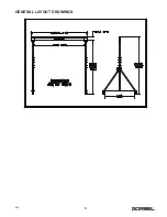
Assemble your Gantry Crane in a clear area free
of obstructions (refer to enclosed
General
Arrangement Drawing
for overall size and other
relevant dimensions).
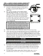
2.2
Assemble the first end support assembly by fully
engaging the upper support weldment into the lower
support weldment such that the overall height is at
its minimum and the holes in both tubes are
correctly oriented relative to one another. Next,
slide assembly apart until the first hole in inner tube
is aligned with outer tube hole. Secure assembly
by inserting the hitch pin assembly through the
holes in both weldment tubes followed by
connecting the snap-on safety hair pin and small
cable (if provided by the manufacturer) to both
ends of the hitch pin. Ensure that the hitch pin
chains are located on the side of the end
support assembly that the eyebolt hole is on
(located on diagonal brace tube (as shown in
Diagram 2B
). Insert eyebolt into threaded hole
and attach chain with open-end chain link.
Repeat with the other end support assembly.
2.3
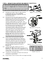
While resting on the floor tilt the I-beam (by
means of rigging (straps/slings are preferred to
reduce paint damage) that is sized and oriented
correctly for raising the load and overhead lifting
device or lift truck) so that the I-beam flange with
the holes is aligned with the top plate holes of
the first end support assembly (as shown in
Diagram 2A
).
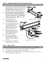
2.4
Install the appropriate hardware (as shown in
Diagram 2C
).
Note:
Bevel washers are used with “S”
beams only. Tighten bolts (refer to
Chart 2A
for proper
torque rating). There must be a minimum of two threads
showing at the end of each bolt.
2.5
Install hoist or hoist trolley (by others) onto I-beam per
manufacturers specifications.
2.6
Repeat steps 2.3 and 2.4 with the other end support assembly.
TIP:
For easiest installation ensure that the end support
weldments are being supported while lying on their side
(as shown in
Diagram 2A
) prior to bolting the I-beam to
them.
TIP:
Be sure that the top plate (located on top of vertical
tubes) length is oriented parallel to the I-beam length.
Diagram 2A.
End Support Assembly.
Diagram 2B.
Hitch Pin Assembly.
Diagram 2C.
Beam to Top Plate Connection.
3
9/19
Chart 2A.
Torque Chart.
Bolt Dia.
Torque
1/2”
60 ft.-lbs.
5/8”
110 ft.-lbs.
3/4”
200 ft.-lbs.


