background image

8

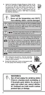
5-3 TEMPERATURE CALIBRATION
 

 (Tip thermometer required)

A. RX-701AS only

1. 

Set the desired temperature using the 

Temperature Setting Knob.

2.  

While measuring the tip temperature with a tip 

thermometer, adjust the CAL (Calibration Screw) 

with Flat-head screwdriver to bring the mea-

sured temperature to the desired temperature 

scale. The tip temperature increases when the 

CAL is turned clockwise, and it decreases when 

the CAL is turned counter-clockwise.

B. RX-711AS only

1.  

Switch the Temperature Display Changeover 

Switch (at the left of the front panel) to SET.

2.  

Set the desired temperature using the 

Temperature Setting Knob.

3.  

While measuring the tip temperature with a tip 

thermometer, adjust the CAL (Calibration Screw) 

with Flat-head screwdriver to bring the mea-

sured temperature to the desired temperature 

scale. The tip temperature increases when the CAL 

is turned clockwise, and it decreases when the 

CAL is turned counter-clockwise.

5.

  Desolder the 3 locations of pins for the 

heater. Remove the heater from the 

PCB.

6.

  Solder the new heater to the PCB. Cut out the extra heater lead wire 3mm 

or less from the PCB.

7.

  Next, about the PCB slot orienta-

tion. The PCB slots are offset from 

center. The longer arc should be up. 

The shorter arc should be down. The 

Earth Pin should be down.

8.

  Reassemble, reversing these steps.

PCB Slot Orientation

Grip Exterior

Earth Pin

PCB

Longer Arc

Shorter Arc

PCB Slot

Ensure the PCB is inserted correctly 

according to the above diagram.

Red Lead 


H

White Lead


S

Yellow Lead 


C

S

C

H

3mmor 

less

Cut

Red Lead 


H

White Lead


S

Yellow Lead 


C

S

C

H

3mmor 

less

Cut

4.

  Disconnect the Earth Connector 

from the Earth Pin; remove 

the sleeve; remove the entire 

assembly, pulling on the Earth 

Collar.

アースーカラー

アースピン

アースコネクタ

Earth Collar

Earth Pin

Earth Connector

Summary of Contents for RX 711AS

Page 1: ...IN THE EVENT OF FAILURE 9 7 SPECIFICATIONS 9 8 REPLACEMENT TIP 10 9 PARTS LIST 11 10 SOLDERING IRON STAND ST 27 INSTRUCTIONS 12 TAIYO ELECTRIC IND CO LTD KEEP THIS MANUAL FOR FUTURE REFERENCE Thank y...

Page 2: ...and bystanders away from the unit 3 Turn off the power when not in use 4 This soldering station is an electrical tool used to solder parts and melt solder Do not use the soldering station for any purp...

Page 3: ...en given supervision or instruction concern ing use of the appliance by a person responsible for their safety Children should be supervised to ensure that they do not play with the appliance 11 Do not...

Page 4: ...ngeover Switch RX 711AS only Protective Cover Fixing Screw Calibration Screw CAL Heat Monitor Lamp Temperature Setting Knob Protective Cover Connector Connector Brass Wool Heat Resistant Sponge Name L...

Page 5: ...he heater will start heating up When the Heat Monitor Lamp flashes the soldering station is ready to use B RX 711AS only 1 Switch the Temperature Display Changeover Switch at the left of the front pan...

Page 6: ...display will not change Ex If the tip is rested on a wet sponge temperature display will continue to show set temperature eg 480 C for approx 10 seconds Then it will start dropping During those 10 sec...

Page 7: ...e heater and remove the oxidized dross inside NOTE Heater Collar Heater Barrel Collar Heater Barrel Spacer Black Collar WARNING CAUTION WARNING CAUTION Never touch the heater barrel collar or adapter...

Page 8: ...ature to the desired temperature scale The tip temperature increases when the CAL is turned clockwise and it decreases when the CAL is turned counter clockwise 5 Desolder the 3 locations of pins for t...

Page 9: ...r if the plastic parts deform Please contact your distributor 4 If the machine is dropped be sure to check the above troubleshooting guide If you notice any signs of damage do not use it and please co...

Page 10: ...5 45 PX 60RT 4C 12 17 4 5 45 PX 60RT 4CR 6 12 17 4 5 45 PX 60RT 3CR 6 17 3 12 5 45 45 PX 60RT 1 2LD 6 25 1 2 0 7 5 PX 60RT 1 6D 6 17 0 5 1 6 5 6 17 0 5 2 4 5 PX 60RT 2 4D 1 8 14 7 5 25 25 1 PX 60RT 1...

Page 11: ...NO Parts Name Code Note Soldering Iron Unit A0883AF00 RX 72GAS Heater B0882AH00 RX 72H Black Collar A0880HW00 RX 72GASAD Spacer A0880HS00 RX 72SS Tip B0672AB00 PX 60RT B Heater Barrel A0880HP00 RX 72H...

Page 12: ...not use the ST 27 near flammable sub stances Always place the stand on a stable worktable or other stable location to prevent injury or accident from dropping it To avoid splattering solder scrap do n...

Page 13: ...the front opening can be adjusted by loosening screws on the side REPLACEMENT PARTS Heat Resistant Sponge ST 53SP Front Opening with adjusting screws ST 27MS Brass Wool 2balls ST 40BW To avoid rust d...

Page 14: ...14...

Page 15: ...15...

Page 16: ...Printed in Japan DECEMBER 2019 A0810AL04...

Reviews: