


6
5.
After setting the temperature, close the protective
cover and tighten the fixing-screw at bottom left with
a Phillips-head screwdriver.
6.
Remove the solder scrap on the iron tip regularly with
the wet sponge of the soldering iron stand.
Approx. 2°C difference between the SET and MEAS display
may occur. In this case, there is no need to adjust the tip
temperature (by knob) on MEAS display. The factory default tip
temperature is set on SET display.
When the temperature display is set to MEAS, there is
a temperature fluctuation from 2°C to 3°C.
It may take time to completely stabilize the temperature. When
accurate temperature control is required, we recommend
waiting 2 minutes after device is switched on.
MEAS display has a 10-second delay. If the temperature
changes for less than 10 seconds, the display will not change.
Ex.) If the tip is rested on a wet sponge, temperature display
will continue to show set temperature (eg. 480°C) for approx.
10 seconds. Then it will start dropping. During those 10
seconds, the temperature-control circuit is working to recover
the set temperature.
NOTE
NOTE
NOTE
NOTE
CAUTION
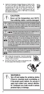
WARNING
Never set the temperature over 500°C.
Your soldering station could be damaged.
Turn off and unplug the soldering station
if there is a burning smell, overheating, or
if the plastic parts deform. Do not use it
again and contact your nearest distribu-
tor. Continued use could result in serious
personal injury or damage.
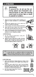
4.
Switch the Temperature Display Changeover Switch (at the
left of the front panel) to MEAS. Display shows the actual
tip temperature. When the Heat Monitor Lamp flashes, the
soldering station is ready to use. However if the unit is
switched ON again with 1 hour of being switched OFF, and
the displayed number is close to “000”, then it is showing
the actual tip temperature.


