Goodman GCH9 Installation Instructions Manual Download Page 17

17

For details concerning connection of pipes to the furnace, refer to
the 

Section IX, Vent/Flue Pipe and Combustion Pipe - Standard

Furnace Connections or Alternate Furnace Connections.

V

ENT

/F

LUE


AND

 C

OMBUSTION

 A

IR

 P

IPE

 L

ENGTHS


AND

 D

IAMETERS

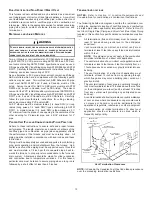
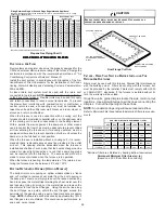
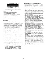
Refer to the following table for applicable length, elbows, and pipe
diameter for construction of the vent/flue and combustion air intake
pipe systems of a direct vent (dual pipe) installation.  The number
of elbows tabulated represents the number of elbows and/or tees
in each (Vent/Flue & Combustion Air Intake) pipe.  Elbows and/or
tees used in the terminations must be included when determining
the number of elbows in the piping systems.
If the combustion air intake pipe is to be installed above a finished
ceiling or other area where dripping of condensate will be objec-
tionable, insulation of the combustion air pipe may be required.
Use 1/2” thick closed cell foam insulation such as Armaflex or
Insultube where required.

Pipe
Siz e 

(4)

(in.)

2

3

4

5

6

7

8

Standard

2

68

65

62

59

56

53

50

A lternate

2

55

52

49

46

43

40

37

Standard

2

68

65

62

59

56

53

50

A lternate

2

55

52

49

46

43

40

37

Standard

2

46

43

40

A lternate

2

33

30

27

Standard

3

68

65

62

59

56

53

50

A lternate

3

55

52

49

46

43

40

37

Standard

3

68

65

62

59

56

53

50

A lternate

3

55

52

49

46

43

40

37

Standard

3

68

65

62

59

56

53

50

A lternate

3

55

52

49

46

43

40

37

090_5

Not Rec ommended

115_5

Dir e ct  V e nt (Dual Pipe )

Max imum A llow able Length of  V ent/Flue & Combus tion

A ir Intake Pipe (f t)

Unit Input

(Btu)

Number of  Elbow s  

(1)(2)(3 )(5)

090_4

V ent/Flue/A ir Intake

Termination

045_3

070_3

070_4

1) Minimum requirement for each vent pipe is five (5) feet in length and one

elbow/tee.

2) Tees and/or elbows used in the vent/flue termination must be included

when determining the number of elbows in the piping system.

3) 3” diameter pipe can be used in place of 2” diameter pipe.
4) Increased Clearance Configurations using (2)  45 deg.  Long Sweep

elbows should be considered equivalent to one 90 deg. elbow.

V

ENT

/F

LUE


AND

 C

OMBUSTION

 A

IR

 P

IPE

 T

ERMINATIONS

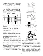
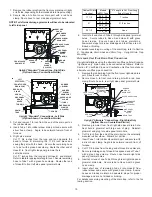
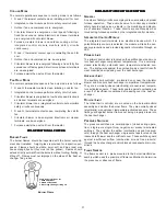
The vent/flue and combustion air pipes may terminate vertically, as
through a roof, or horizontally, as through an outside wall.
Vertical pipe terminations should be as shown in the following
figure.  

Refer to Section IX, Vent/Flue Pipe and Combustion Pipe -

Termination Locations

 for details concerning location restrictions.

The penetrations through the roof must be sealed tight with proper
flashing such as is used with a plastic plumbing vent.

TEE

12" MIN.

12" MIN.

TO ROOF OR

HIGHEST

ANTICIPATED
 SNOW LEVEL

VENT/FLUE

90º

MEDIUM RADIUS

ELBOWS

COMBUSTION

AIR INTAKE

24" MAX.
3" MIN.

SCREEN

Vertical Terminations (Dual Pipe)

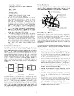
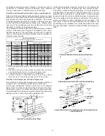
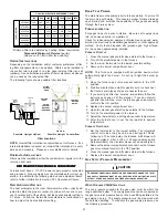
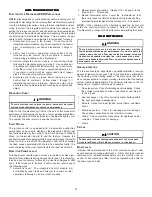
Horizontal terminations should be as shown in the following fig-
ure.  Refer to 

Section IX, Vent/Flue Pipe and Combustion Pipe -

Termination Location

 for location restrictions.  A 2 3/8 inch diameter

wall penetration is required for 2” diameter pipe while a 3 1/2 inch
diameter hole is required for 3” diameter pipe.  To secure the pipe
passing through the wall and prohibit damage to piping connec-
tions, a coupling should be installed on either side of the wall and
solvent cemented to a pipe connecting the two couplings.  The
pipe length  should be the wall thickness plus the depth of the
socket fittings to be installed on the inside and outside of the wall.
The wall penetration should be sealed with silicone caulking ma-
terial.

12" MIN

3" MIN

24" MAX

3" MIN

24" MAX

Standard Horizontal Terminations (Dual Pipe)

24" MAX

3" MIN

24" MAX

    AIR
INTAKE

     90°
MEDIUM 
RADIUS
ELBOW

Alternate Horizontal Vent Termination (Dual Pipe)
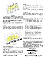
SUPPORT 

STRAPS

     90°
MEDIUM 
RADIUS
ELBOWS

12" MIN.

VENT/FLUE

TEE

SCREEN

COMBUSTION
AIR INTAKE.

     12" MIN. ABOVE

HIGHEST ANTICIPATED

 SNOW LEVEL

     12" MIN. ABOVE

HIGHEST ANTICIPATED

 SNOW LEVEL

3" MIN.

24" MAX.

12" MIN

Standard Horizontal Terminations Above Anticipated Snow

Level (Dual Pipe)

Summary of Contents for GCH9

Page 1: ...tall the product safely and to know it well enough to be able to instruct a customer in its safe use Safety is a matter of common sense a matter of thinking before acting Most dealers have a list of s...

Page 2: ...ER VENT FLUE AND COMBUSTION AIR PIPING PRACTICES 13 TERMINATION LOCATIONS 13 CANADIAN VENTING REQUIREMENTS 14 STANDARD FURNACE CONNECTIONS 14 ALTERNATE FURNACE CONNECTIONS 14 NON DIRECT VENT SINGLE PI...

Page 3: ...XVIII Troubleshooting 32 ELECTROSTATIC DISCHARGE ESD PRECAUTIONS 32 DIAGNOSTIC CHART 32 FAULT RECALL 32 RESETTING FROM LOCKOUT 32 XIX Maintenance 32 ANNUAL INSPECTION 32 FILTERS 32 BURNERS 33 INDUCED...

Page 4: ...warranty certificate is also supplied with the unit Read the warranty carefully and note what is covered Keep the warranty cer tificate in a safe location for future reference If additional informatio...

Page 5: ...e Pipe Connection Alternate 15 Rubber Elbow 16 Induced Draft Blower 17 Electrical Connection Inlets Alternate 18 Coil Front Cover Pressure Tap 19 Coil Front Cover Drain Port 20 Drain Line Penetrations...

Page 6: ...The input rate and temperature rise are set per the furnace rating plate 100 outside air is provided for combustion air requirements during construction Temporary ducting can be used II SAFETY II SAF...

Page 7: ...ly air opening and the combustible floor Exposure to contaminated combustion air will result in safety and performance related problems Do not install the furnace where the combustion air is exposed t...

Page 8: ...tions of use g If improper venting is observed during any of the above tests the common venting system must be corrected halogen type refrigerants cleaning solutions such as perchloroethylene printing...

Page 9: ...ipping heavily insulated caulked vapor barrier etc addi tional air may need to be provided using the methods described in 5 3 3 b or 5 3 4 Space Unconfined For purposes of this Code a space whose volu...

Page 10: ...directly with an additional room s of sufficient volume so that the combined volume of all spaces meets the criteria for an unconfined space The total input of all gas utilization equipment installed...

Page 11: ...ropriate in stallation positions ductwork connections and resulting airflow arrangements VII HO VII HO VII HO VII HO VII HORIZO RIZO RIZO RIZO RIZONT NT NT NT NTAL APPLI AL APPLI AL APPLI AL APPLI AL...

Page 12: ...s require an orifice change to compensate for the energy content difference between natural and propane gas High altitude installations may require both a pressure switch and an orifice change These c...

Page 13: ...nt flue pipe and a combustion air intake pipe Refer to the appropriate section for details concerning piping size length number of elbows furnace connections and terminations MATERIALS AND JOINING MET...

Page 14: ...rd against inadvertent blockage COMBUSTION AIR PIPE DIRECT VENT INSTALLATIONS On upflow units secure the combustion air intake pipe directly to the air intake coupling On counterflow units secure the...

Page 15: ...LT IN LEAKS CAUSING BODILY INJURY OR DEATH DUE TO EXPOSURE TO FLUE GASES INCLUDING CARBON MONOXIDE 7 Upflow and Counterflow units For upright installations externally mount the rubber elbow to the ven...

Page 16: ...r of elbows in the piping system Pipe Size 4 inc 2 3 4 5 6 7 8 045_3 2 68 65 62 59 56 53 50 070_3 2 68 65 62 59 56 53 50 070_4 2 46 43 40 2 16 13 10 3 68 65 62 59 56 53 50 090_5 3 68 65 62 59 56 53 50...

Page 17: ...ter pipe can be used in place of 2 diameter pipe 4 Increased Clearance Configurations using 2 45 deg Long Sweep elbows should be considered equivalent to one 90 deg elbow VENT FLUE AND COMBUSTION AIR...

Page 18: ...furnace NOTE If the alternate vent flue outlet is utilized in an upright installation the drain trap and drain connections must be located on the same side as the alternate vent flue outlet In horizon...

Page 19: ...Hose B with green hose clamps Ensure hoses and tubes maintain a downward slope for proper drainage and that they are not kinked or binding For details concerning mounting of the drain trap refer to S...

Page 20: ...ht down side panel grommet holes Secure tubes to Hose A and Hose B using green hose clamps Ensure hoses and tubes maintain a downward slope for proper drainage and are not kinked or bound For details...

Page 21: ...must be sized in accordance with the maximum overcurrent pro tection specified on the unit rating plate An electrical disconnect must be provided at the furnace location NOTE Line polarity must be ob...

Page 22: ...Blower pressure switch is powered anytime the pressure switch is closed and provides 24 VAC humidifier control Remove the yellow wire and connect the supplied brown jumper wire to the pressure switch...

Page 23: ...plying the furnace must be properly sized based on the gas flow required specific gravity of the gas and length of the run The gas line installation must comply with local codes or in their absence wi...

Page 24: ...ctors and semi rigid tubing against physical and thermal damage when installed Ensure aluminum alloy tubing and connectors are coated to protect against external corrosion when in contact with masonry...

Page 25: ...ne gas leak Rust can reduce the level of odorant in propane gas Do not rely on your sense of smell Contact a local propane gas supplier about installing a gas detecting warning system If the presence...

Page 26: ...uipped with means to prevent operation of either unit unless the damper is in the full heat or cool position When the furnace is installed without a cooling coil it is recom mended that a removable ac...

Page 27: ...bility of flue gases escaping through the drain system FURNACE OPERATION Purge gas lines of air prior to startup Be sure not to purge lines into an enclosed burner compartment Check for leaks using an...

Page 28: ...NT UNRELIABLE OPERATION OR EQUIPMENT DAMAGE THE GAS MANIFOLD PRESSURE MUST BE AS SPECIFIED ON THE UNIT RATING PLATE ONLY MINOR ADJUSTMENTS SHOULD BE MADE BY ADJUSTING THE GAS VALVE PRESSURE REGULATOR...

Page 29: ...rtially open position 2 Place thermometers in the return and supply ducts as close to the furnace as possible Thermometers must not be influenced by radiant heat by being able to see the heat exchange...

Page 30: ...MODE DIP SWITCH IS SET TO 2 STG POSITION The normal operational sequence in sequence is as follows R and W thermostat contacts close initiating a call for heat Integrated control module performs safet...

Page 31: ...Y CIRCUIT DESCRIPTION XVII SAFETY CIRCUIT DESCRIPTION XVII SAFETY CIRCUIT DESCRIPTION XVII SAFETY CIRCUIT DESCRIPTION GENERAL A number of safety circuits are employed to ensure safe and proper furnace...

Page 32: ...e least recent fault RESETTING FROM LOCKOUT Furnace lockout results when a furnace is unable to achieve igni tion after three attempts during a single call for heat It is character ized by a non funct...

Page 33: ...AME SENSOR QUALIFIED SERVICER ONLY Under some conditions the fuel or air supply can create a nearly invisible coating on the flame sensor This coating acts as an insulator causing a drop in the flame...

Page 34: ...E LEA RE LEA RE LEAVIN VIN VIN VIN VING AN INST G AN INST G AN INST G AN INST G AN INSTALL ALL ALL ALL ALLA A A A ATI TI TI TI TIO O O O ON N N N N Cycle the furnace with the thermostat at least three...

Page 35: ...kage proper length elbows and termination Check drain system Correct as necessary Correct pressure switch setpoint or contact motion Tighten or correct wiring connection Pressure switch hose blocked p...

Page 36: ...e due to improper gas pressure or combustion air Induced draft blower and circulator blower runs continuously No furnace operation Integrated control module diagnostic LED is flashing FIVE 5 flashes F...

Page 37: ...NT COVER PRESSURE SWITCH N O C GY BK PLUG CONNECTION FIELD SPLICE SWITCH TEMP OR 24V THERMOSTAT CONNECTIONS GR GND 115 VAC 24 VAC BLOWER COMPARTMENT DOOR SWITCH OPEN WHEN DOOR OPEN DOOR SWITCH BK GND...

Reviews: