background image

8

IO-247A

     12/04

safety exhaust, odor control, and air for compressors.

(d) In addition to air needed for combustion, air shall be supplied

for ventilation, including all air required for comfort and
proper working conditions for personnel.

(e) While all forms of building construction cannot be covered

in detail, air for combustion, ventilation and dilution of flue
gases for gas utilization equipment vented by natural draft
normally may be obtained by application of one of the
methods covered in 5.3.3 and 5.3.4.

(f) Air requirements for the operation of exhaust fans, kitchen

ventilation systems, clothes dryers, and fireplaces shall be
considered in determining the adequacy of a space to
provide combustion air requirements.

5.3.2 Equipment Located in Unconfined Spaces:

In unconfined spaces (see definition below) in buildings,
infiltration may be adequate to provide air for combustion
ventilation and dilution of flue gases. However, in buildings
of tight construction (for example, weather stripping, heavily
insulated, caulked, vapor barrier, etc.), additional air may
need to be provided using the methods described in 5.3.3-
b or 5.3.4.

Space, Unconfined.

For purposes of this Code, a space whose volume is not
less than 50 cubic feet per 1,000 BTU per hour of the
aggregate input rating of all appliances installed in that
space. Rooms communicating directly with the space in
which the appliances are installed through openings not
furnished with doors, are considered a part of the unconfined
space.

5.3.3 Equipment Located in Confined Spaces:

(a) 

All Air from Inside the Building: 

The confined space shall be

provided with two permanent openings communicating
directly with an additional room(s) of sufficient volume so
that the combined volume of all spaces meets the criteria
for an unconfined space. The total input of all gas utilization
equipment installed in the combined space shall be
considered in making this determination. Each opening shall
have a minimum free area of 1 square inch per 1,000 BTU
per hour of the total input rating of all gas utilization
equipment in the confined space, but not less than 100
square inches. One opening shall be within 12 inches of the
top and one within 12 inches of the bottom of the enclosure.
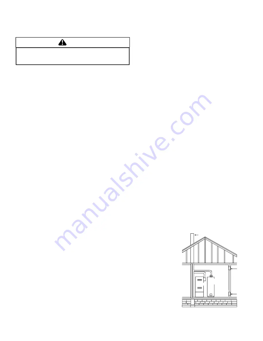
Furnace

Water
Heater

Opening

Chimney or Gas Vent

Opening

NOTE: Each opening must have
a free area of not less than one 
square inch per 1000 BTU of  
the total input rating of all equip-
ment in the enclosure, but not
less than 100 square inches.

Equipment Located in Confined Spaces;

All Air from Inside Building. See 5.3.3-a.

Consult the instructions packaged with the thermostat for mounting
instructions and further precautions.

V. COMBUSTION AND VENTILATION AIR REQUIREMENTS

W A R N IN G

T

O   A V O ID   P R O P E R T Y   D A M A G E ,  P E R S O N A L   IN J U R Y   O R   D E A T H ,  S U F F IC IE N T

F R E S H   A IR   F O R   P R O P E R   C O M B U S T IO N   A N D   V E NT IL A T IO N   O F   F L U E   G AS E S   M U S T

B E   S U P P L IE D . 

M

O S T   H O M E S   R E Q U IR E   O U T S ID E   A IR   B E   S U P P L IE D  IN T O   T HE

F U R N A CE   A RE A .

Improved construction and additional insulation in buildings have
reduced heat loss by reducing air infiltration and escape around
doors and windows.  These changes have helped in reducing
heating/cooling costs but have created a problem supplying
combustion and ventilation air for gas fired and other fuel burning
appliances.  Appliances that pull air out of the house (clothes dryers,
exhaust fans, fireplaces, etc.) increase the problem by starving
appliances for air.

House depressurization can cause back drafting or improper
combustion of gas-fired appliances, thereby exposing building
occupants to gas combustion products that could include carbon
monoxide.

If this furnace is to be installed in the same space with other gas
appliances, such as a water heater, ensure there is an adequate
supply of combustion and ventilation air for the other appliances.
Refer to the latest edition of the National Fuel Gas Code NFPA 54/
ANSI Z223.1 (Section 5.3), or CAN/CSA B149 Installation Codes
(Sections 7.2, 7.3, or 7.4), or applicable provisions of the local
building codes for determining the combustion air requirements for
the appliances.

This furnace must use indoor air for combustion. It cannot be
installed as a direct vent (i.e., sealed combustion) furnace.

Most homes will require outside air be supplied to the furnace area
by means of ventilation grilles or ducts connecting directly to the
outdoors or spaces open to the outdoors such as attics or crawl
spaces.

The following information on air for combustion and ventilation is
reproduced from the

 National Fuel Gas Code NFPA 54/ANSI

Z223.1 Section 5.3.

5.3.1 General:

(a) The provisions of 5.3 apply to gas utilization equipment

installed in buildings and which require air for combustion,
ventilation and dilution of flue gases from within the building.
They do not apply to (1) direct vent equipment which is
constructed and installed so that all air for combustion is
obtained from the outside atmosphere and all flue gases are
discharged to the outside atmosphere, or (2) enclosed
furnaces which incorporate an integral total enclosure and
use only outside air for combustion and dilution of flue gases.

(b) Equipment shall be installed in a location in which the facilities

for ventilation permit satisfactory combustion of gas, proper
venting and the maintenance of ambient temperature at safe
limits under normal conditions of use. Equipment shall be
located so as not to interfere with proper circulation of air.
When normal infiltration does not provide the necessary air,
outside air shall be introduced.

(c) In addition to air needed for combustion, process air shall

be provided as required for: cooling of equipment or material,
controlling dew point, heating, drying, oxidation or dilution,

Summary of Contents for AMV8

Page 1: ...than when the unit is in operation Remember it is your responsibility to install the product safely and to know it well enough to be able to instruct a customer in its safe use Safety is a matter of...

Page 2: ...INSTALLATION 13 FIX 1 LINER TERMINATION 13 FIX 2 CHANGE VENTING ARRANGEMENTS 13 FIX 3 REBUILD THE CROWN 13 FIX 4 RELINING 13 VIII Electrical Connections 14 WIRING HARNESS 14 115 VOLT LINE CONNECTIONS...

Page 3: ...7 ANNUAL INSPECTION 27 FILTERS 27 FILTER MAINTENANCE 27 FILTER REMOVAL 27 UPRIGHT FILTER REMOVAL 27 INDUCED DRAFT AND CIRCULATOR BLOWER MOTORS 28 FLAME SENSOR QUALIFIED SERVICER ONLY 28 IGNITER QUALIF...

Page 4: ...mponent failures could result in heating system operational problems TO THE INSTALLER Before installing this unit please read this manual thoroughly to familiarize yourself with specific items which m...

Page 5: ...uring grounding will be discharged 3 Service integrated control module or connecting wiring following the discharge process in step 2 Use caution not to recharge your body with static electricity i e...

Page 6: ...s permitted when installed in the horizontal configuration Line contact is defined as the portion of the cabinet that is formed by the intersection of the top and side National Fire Protection Associa...

Page 7: ...nting system are not in operation a Seal any unused openings in the venting system b Inspect the venting system for proper size and horizontal pitch as required by the National Fuel Gas Code ANSI Z223...

Page 8: ...AM AGE PERSONAL INJURY OR DEATH SUFFICIENT FRESH AIR FO R PROPER COM BUSTION AND VENTILATION OF FLUE G ASES M UST BE SUPPLIED MO ST HOM ES REQ UIRE OUTSIDE AIR BE SUPPLIED INTO THE FURNACE AREA Improv...

Page 9: ...input rating of all equipment in the enclosure Furnace Water Heater Chimney or Gas Vent NOTE The air duct openings must have a free area of not less than one square inch per 2000 BTU of the total inp...

Page 10: ...W 70 4 Inch 90 4 Inch 115 N A 140 N A MODEL Under some conditions larger vents than those shown above may be required or allowed When an existing furnace is removed from a venting system serving other...

Page 11: ...ter Water Heater Vent Connector Basement Floor F A F Vent Connector Figure 8 Typical Multiple Flue Clay Tile Chimney CHECKLIST SUMMARY This checklist serves as a summary of the items to be checked bef...

Page 12: ...must be removed and replaced Fix 4 Next gently tap the inside of the liner with a Phillips screwdriver If the screwdriver perforates the liner or if the tapping does not sound like metal hitting metal...

Page 13: ...acturer s instructions In some cases a shorter extension above the roof may be possible with a liner than would be required with a masonry chimney For further information on relining see Fix 4 FIX 2 C...

Page 14: ...s that have the junction box located in the include indoor swimming pools and chlorine bleaches paint strippers adhesives paints varnishes sealers waxes which are not yet dried and solvents used durin...

Page 15: ...switch 24 VOLT THERMOSTAT WIRING NOTE Wire routing must not interfere with circulator blower operation filter removal or routine maintenance As a two stage furnace the furnace integrated control modul...

Page 16: ...furnace integrated control module 4 Secure the dehumidistat ground wire typically the green lead to the ground screw on the furnace junction box NOTE Ground wire may not be present on all dehumidista...

Page 17: ...own on the rating plate Overfiring of the furnace can result in premature heat exchanger failure Gas pressures in excess of 13 inches water column can also cause permanent damage to the gas valve IMPO...

Page 18: ...pressure switch kits PROPANE GAS CONVERSION WARNING POSSIBLE PROPERTY DAMAGE PERSONAL INJURY OR DEATH MAY OCCUR IF THE CORRECT CONVERSION KITS ARE NOT INSTALLED THE APPROPRIATE KITS MUST BE APPLIED TO...

Page 19: ...h the left side of the furnace the installer must supply the following fittings starting from the gas valve Straight pipe to reach the exterior of the furnace A ground joint union drip leg and manual...

Page 20: ...9 1 559 50 18 37 79 131 198 376 114 237 448 913 1 417 60 16 35 72 121 187 340 103 217 409 834 1 275 80 13 29 62 104 155 289 89 185 346 724 1 066 100 11 26 55 90 138 255 78 162 307 630 976 125 10 24 48...

Page 21: ...waits call from thermostat NORMAL HEATING SEQUENCE R and W1 or R and W1 W2 thermostat contacts close initiating a call for heat Integrated control module performs safety circuit checks Induced draft b...

Page 22: ...blower requires 30 seconds to ramp up to full speed Electronic air cleaner terminals are energized with circulator blower Furnace circulator blower and outdoor cooling unit run their appropriate spee...

Page 23: ...Installation s gas heating HTG value 1 000 BTU ft3 Obtained from gas supplier Installation s seconds per cubic foot 34 sec ft3 Conversion Factor hours to seconds 3600 sec hr Input Htg value x 3600 sec...

Page 24: ...r the cooling system Most cooling systems are designed to work with air flows between 350 and 450 CFM per ton Most manufacturers recommend an air flow of about 400 CFM per ton Example 2 5 tons X 400 C...

Page 25: ...ormance to be optimized for the particular homeowner s needs O F F O F F 8 7 4 3 2 1 O F F O N 4 3 2 1 O N O F F 4 3 2 1 O N O N 4 3 2 1 Cooling Speed Tap A Cooling Speed Tap B Cooling Speed Tap C Coo...

Page 26: ...ontrol will reset and allow the furnace to resume normal operation WARNING TO PREVENT PREMATURE FAILURE OF HEAT EXCHANGER PROPERTY DAMAGE PERSONAL INJURY OR DEATH DO NOT ADJUST THE LIMIT CONTROL FACTO...

Page 27: ...n determining the cause XVI MAINTENANCE WARNING TO AVOID ELECTRICAL SHOCK INJURY OR DEATH DISCONNECT ELECTRICAL POWER BEFORE PERFORMING ANY MAINTENANCE IF YOU MUST HANDLE THE IGNITER HANDLE WITH CARE...

Page 28: ...VENT PERSONAL INJURY OR DEATH DO NOT REMOVE ANY INTERNAL COMPARTMENT COVERS OR ATTEMPT ANY ADJUSTMENT ELECTRICAL COMPONENTS ARE CONTAINED IN BOTH COMPARTMENTS CONTACT A QUALIFIED SERVICE AGENT AT ONCE...

Page 29: ...circuit Inspect pressure switch hose Repair if necessary Inspect flue for blockage proper length elbows and termination Correct pressure switch setpoint or contact motion Tighten or correct wiring con...

Page 30: ...spect for proper sensor alignment Check inlet air piping for blockage proper length elbows and termination Compare current gas pressure to rating plate info Adjust as needed Turn power OFF prior to re...

Page 31: ...MIT CONTROL WIRING TO UNIT MUST BE PROPERLY ON S OME M O DE LS IN DU CTO R COI L P R ES SU R E SWI TC H LO W FIR E Y L RD BK WH IN D U CED B R GN D WH WH BK BR RD GN BU BR WH AU XI LIA RY LI M I T C O...

Page 32: ...of product failure They are simple to service and forgiving to operate We use quality materials and components Finally every unit is run tested before it leaves the factory That s why we know There s...

Reviews: