31
WIRING DIAGRAMS
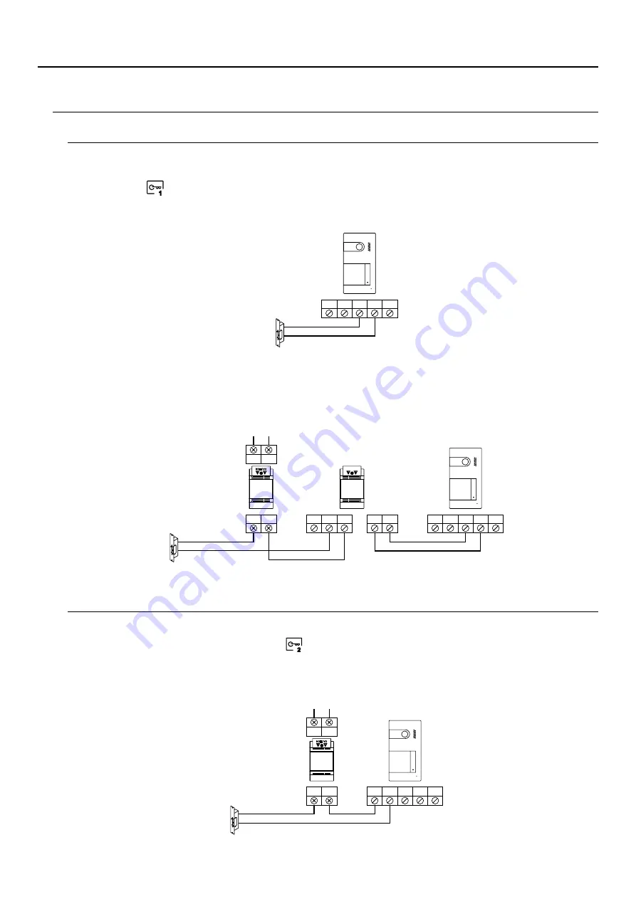
Connection of a lock release
Connection of an auxiliary device at the relay output
The drawing shows the connection of a 12Vdc lock release, with a maximum consumption of 270mA. The use of
Golmar CV-14/DC, CV-24/DC, CV-14P/UNI or CV-24P/UNI models is recommended. Activation is carried out
through icon
.
The activation time is 3 seconds, with the possibility of setting it to between 0.5 and 10 seconds (see pp. 3 -3 ).
3 4
The activation time is 3 seconds, with the possibility of setting it to between 0.5 and 10 seconds (see pp. 3 -3 ).
3 4
The drawing, by way of example, shows the connection of a second AC lock release. The relay can switch 6A/24V
loads. Activation is carried out through icon
.
If the lock release to be used is alternating current, use a relay and transformer suitable for the consumption, as
well as the varistor supplied. The example shows a Golmar SAR-12/24 relay and a TF-104 transformer
(12Vac/1.5A).
CV-
BUS
CV+ AP+
BUS
CV-
BUS
CV+ AP+
BUS
IN
IN
C
NC
NA
PRI
PRI
Mains
100~240Vac
SEC
SEC
GND
C
CCTV AP-
NA
PRI
PRI
ains
M
100~240Vac
SEC
SEC
1
2
SOUL PANEL/4.3
SOUL PANEL/4.3
SOUL PANEL/4.3
SAR-12/24
TF-104
SOUL S5110/ART 4 VIDEO DOOR ENTRY SYSTEM KIT


