background image

Operating Instructions

8.3  Viewing the Controller 

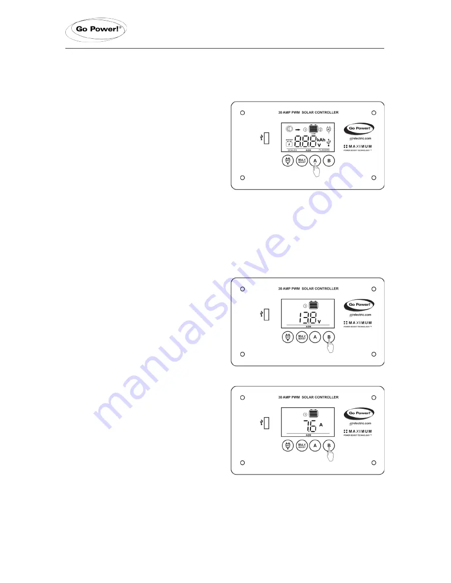
Display Information

The GP-PWM-30 has two modes to 

watch the display information, manual 

and auto scroll.You can change between 

the  two  modes  by  holding  down  the                

A Button

 for 3 seconds.

Mode 1-


 Manually  Scroll  Through                   

Display Information 

Battery 1 Status Values

To toggle between Battery Voltage, PV 

Charging Current and Battery State 

of  Charge  (SOC)  for  Battery  1  and  2,              

press the 

B Button

Battery 1 Voltage Screen

Push the 

B Button

 to show the                       

voltage for Battery 1.

Icons Displayed:

 Battery SOC,                    

Volt Symbol (V), Symbol 1

Battery 1 Current Screen

Push the 

B Button

 to show the PV 

charging current for battery 1. The            

GP-PWM-30 will begin to limit the              

current as Battery 1 reaches a full 

charge. The current that is not used for 

Battery 1, is used to charge Battery 2.

Icons Displayed:

 Arrow, Ampere     

Symbol (A), Battery SOC, Symbol 1

page 13

Summary of Contents for GP-PWM-30

Page 1: ...GP PWM 30 User Manual 30 AMP PWM SOLAR CONTROLLER 2015 Go Power By Carmanah Technologies 77727_MANUAL_GP PWM 30_vE powered by Solid Signal www solidsignal com info solidsignal com 1 877 312 4547...

Page 2: ...isplay Symbols 10 8 Operating Instructions 11 8 1 Power Up 11 8 2 Setting the Battery Type and Charging Profile 11 8 3 Viewing the Controller Display Information 13 8 4 Battery Charging Profile Chart...

Page 3: ...The GP PWM 30 is a 12 volt flush mounted photovoltaic PV charge controller rated for a continuous solar current input of 30 amps The GP PWM 30 uses Pulse Width Modulation PWM technology and a unique f...

Page 4: ...Battery 2 Voltage Range 6V 15 5V Max Solar Voltage 28V Operating Consumption Display backlight on 16mA Operating Consumption Display backlight off 6mA Bulk Absorption Voltage Sealed Gel AGM Flooded 14...

Page 5: ...installation Use extreme caution when working with electricity and when handling and working around batteries Observe correct polarity Reverse polarity of the battery terminals and array will cause th...

Page 6: ...ositive and negative battery connections must connect directly from the controller to the batteries Use of a positive or negative distribution bus is allowed between the controller and battery as long...

Page 7: ...Module Terminal Screw Torque 14 Wire Gauge 12 Wire Gauge 10 Wire Gauge 10 Wire Gauge 10 Wire Gauge 10 Wire Gauge 10 Wire Gauge 16 inch pounds 1 8N m IMPORTANT Identify the polarity positive and negati...

Page 8: ...arge 6 Re torque After 30 days of operation re torque all terminal screws to ensure the wires are properly secured to the controller The GP PWM 30 is based on a 30 amp max input from the solar modules...

Page 9: ...anel to the controller IMPORTANT Ensure your primary permanent battery house bank is connected to the battery 1 terminals Connect your secondary battery starting trolling to battery 2 terminals only Y...

Page 10: ...11 0V 7 Battery Type Profiles Sealed Gel AGM Flooded 8 Boost Mode Controller tries to keep battery at boost voltage or higher If whole display is blinking Battery 1 voltage is greater than 15 5V If Ba...

Page 11: ...t on page 15 for more details 8 2 Setting the Battery Type and Charging Profile To select the battery charging profile press and hold the B Button This will cause the current battery type to blink Set...

Page 12: ...ry profile press and hold the A Button for 3 seconds If there is not a second battery connected to the controller or if the second battery is connected with reverse polarity the controller will not pr...

Page 13: ...Voltage PV Charging Current and Battery State of Charge SOC for Battery 1 and 2 press the B Button Battery 1 Voltage Screen Push the B Button to show the voltage for Battery 1 Icons Displayed Battery...

Page 14: ...ormation for Battery 1 Battery 1 State of Charge Screen The battery state of charge is shown as a percentage Icons Displayed Battery SOC Percent Symbol Symbol 1 Battery 2 Status Values Battery 2 Volta...

Page 15: ...AGM and FLOODED are generic battery designations Choose the charging profile that works best with your battery manufacturer s recommendations Auto Equalize The GP PWM 30 has an automatic equalize feat...

Page 16: ...attery 1 drops below 6 volts Low battery 2 If the battery 2 state of charge reaches 0 the battery SOC symbol will show the text LOW beneath it The controller will continue operating in this condition...

Page 17: ...nstructions included with the inverter Then connect the modular cable found in the inverter remote box to the remote terminal of the inverter and to the remote terminal of the GP PWM 30 marked with an...

Page 18: ...There are numerous events that may appear as problems but are in fact perfectly normal Please visit gpelectric com for the most up to date FAQs 1 It seems like my flooded batteries are losing water o...

Page 19: ...ltage reading at controller battery terminals the problem is in the wiring between the battery and the controller If the battery voltage is lower than 6 volts the controller will not function 3 For th...

Page 20: ...ration and or wiring connections and or wire gauge 3 Dirty or shaded module or lack of sun 4 Blown diode in solar module when two or more modules are connected in parallel 1 Battery State of Charge sc...

Page 21: ...epartment please read the frequently asked questions section of our website to troubleshoot the problem If trouble persists Unless approved by Go Power management all product shipped collect to Go Pow...

Page 22: ...14 Installation Template Use the template on page 23 for flush mounting the controller page 22...

Page 23: ......

Reviews: