background image

16

INSTALLATION

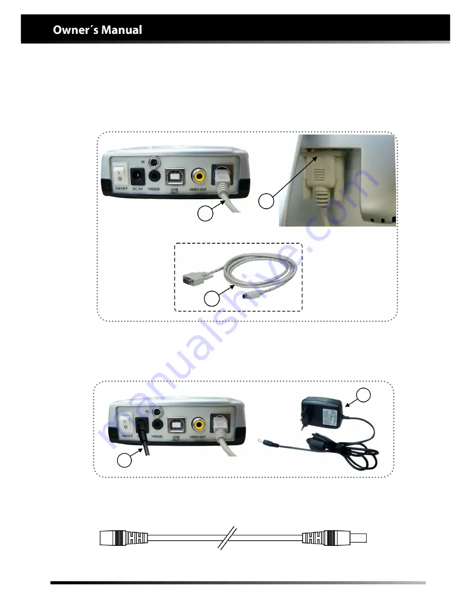
Installation of the camera in the “Monitor”

C) Connect the end of the VGA video cable (4) to the module (5) and the other end (6) 

to the monitor.

5

6

4

D) Connect the camera Power supply source (7) to the electrical network and the other 

end to the module (8).

8

7

In order to install the camera on the column of the light, it is necessary to use the cables 

below. The installation should only be executed by Gnatus authorized technicians.

Complementary cable

Summary of Contents for In Cam LX Camera

Page 1: ......

Page 2: ...to S P Brasil Fone 55 16 2102 5000 Fax 55 16 2102 5001 C N P J 48 015 119 0001 64 Insc Est 582 329 957 115 www gnatus com br gnatus gnatus com br Technical Duties Gilberto Henrique Canesin Nomelini CREA SP 0600891412 INSTRUCTIONS FOR USE ATTENTION For greater safety Read and understand all the instructions contained in these Instructions for Use before installing or operating this Equipment Note T...

Page 3: ...ns for preserving the equipment 35 Precautions and warnings during the installation of equipment 36 Precautions and warnings during the use of equipment 36 Precautions and warnings after the use of equipment 37 Precautions and warnings during the cleaning and disinfection of equipment 37 Precautions in case of alteration in the functioning of equipment 37 Precautions to be adopted against foreseea...

Page 4: ...ts available in the World This manual is a general presentation of your product and it will give you important details to help you to solve possible problems Please read it and keep this with you Identification Technical Name Camera Image Recorder Brand Name In Cam LX Camera Model In Cam LX Camera Brand GNATUS DESCRIPTION OF THE EQUIPMENT ...

Page 5: ...der Light table module compact and functional with interfaces for diverse applications allows connections in VGA monitors TV and Computer Remote control with programming and image selection functions allows greater mobility in control and storage of captured images Handpiece communication cable in highly flexible material allows flexibility and does not have the fragility found in fiber optic cabl...

Page 6: ...6 MODULES ACCESSORIES OPTIONS AND MATERIALS OF CONSUMPTION A Handpiece In Cam LX Camera B Module A B ...

Page 7: ...duct 01 Power supply source 100 240V camera 02 Video VGA cable 03 Protective cover 04 Camera cable 05 Video RCA cable 06 USB cable 07 Sensor IR Cable 08 Supplemental cable 09 Camera holder 10 Camera holder fastening screw 11 Software installation CD for capturing and storage of images 12 Remote IR control ...

Page 8: ...water penetration IPX 0 Mode of Operation Continuous Model In Cam LX Camera Capture element 1 4 Color CCD Gain control Automatic Power 14VA 100V 17VA 240V Video output 1 0Vp p Composite 75ohm Resolution 480 TV Line Electronic shutter Automatic 1 60 1 50 1 100 000seg Power supply Ve 100 240V 50 60 Hz Vs 5V 2A Focal Distance 2mm 40mm Freezing On the handpiece button 60 blown up frozen images total o...

Page 9: ...024 pixels Lighting 6 LEDs Handpiece weight 89g Net weight 900 g Gross weight 1 030 Kg The video monitor used combined with the In Cam Lx Camera must present the following minimum configuration Power 100 240VAC 50 60Hz Internal source in the monitor Vídeo signal RGB Analogical USB VGA Contrast 30 000 1 DFC Response time 8ms Angle of vision H 176º V 170º ...

Page 10: ...10 TECHNICAL SPECIFICATIONS Eletromagnetic emissions ...

Page 11: ...11 TECHNICAL SPECIFICATIONS ...

Page 12: ...12 TECHNICAL SPECIFICATIONS ...

Page 13: ...ISO 13485 2003 Quality systems medical devices IEC 60601 1 2 2007 Collateral Standard Eletromagnetic Compatibility ISO 9001 2008 Quality Management System Requirements RDC 59 2000 Boas práticas de fabricação de produtos médicos ANVISA Norms employed The materials used to produce the equipment are Biocompatible The video monitor and In Cam Lx Camera set is appropriated for use inside the patient s ...

Page 14: ...Contentofaccessibleandnon accessible demarcations Gnatus bears no responsibility for damages or accidents caused by poor installation executed by a technician not authorized by Gnatus Only after the equipment has been installed and duly tested by the authorized technician representing Gnatus will it be ready to start work operations OBS These information also make part of the Manual of Installatio...

Page 15: ...lease contact the Gnatus technical assistance Note The camera can be installed directly in the monitor or the computer using the software of capturing and storing images The video monitor used combined with the In Cam Lx Camera must be according with the guidelines IEC 60 950 IEC 801 3 Installation of the camera in the Monitor A Connect one of the sides of the camera cable 1 to the module 2 and th...

Page 16: ...her end 6 to the monitor 5 6 4 D Connect the camera Power supply source 7 to the electrical network and the other end to the module 8 8 7 In order to install the camera on the column of the light it is necessary to use the cables below The installation should only be executed by Gnatus authorized technicians Complementary cable ...

Page 17: ...ce input located in the back of the computer Fixation of the camera holder in the ruler of the holder monitor To install the holder of the camera A in the ruler of the holder monitor B use a Phillips screwdriver and release the 2 screws C that match the piece A and D Discard pieces C and D because they will no longer be used attach the piece A in the ruler B using the 2 screws E Remembering that i...

Page 18: ...18 INSTALLATION ...

Page 19: ...19 Installation of the camera Driver INSTALLATION A Insert the camera installation CD enter into the D CD driver and click on setup for installation of the driver B Wait for installation of the driver ...

Page 20: ...20 Installation of the camera Driver INSTALLATION C Click on forward D Click on finish ...

Page 21: ...21 Installation of the camera Driver INSTALLATION E After termination of installation click on Yes to restart the computer and click on finish ...

Page 22: ...22 Installation of the camera Software INSTALLATION B Click on Next to continue A Enter once more in the D CD driver and click on Camera Software for installation of the camera software ...

Page 23: ...23 Installation of the camera Software INSTALLATION C Click on Next to continue D Click on Next to continue ...

Page 24: ...24 Installation of the camera Software INSTALLATION E The software icon will appear in the upper corner of the Desktop ...

Page 25: ... 1 image per screen 4 Grids Screen Captures up to 240 images there being 4 images per screen C Responsible for illuminating the operating field 1 C A B ATTENTION In order to use the camera it is indispensable to use the protective cover or film of PVC avoiding risks of cross contamination Turn on the monitor and the module using the on off power switch 1 positioned on the back of it Next turn on t...

Page 26: ...ids mode it is possible to zoom in on only one image of the quadrant Press once more to return to the normal size 5 Exclude 1 Image This function will erase a single image that is shown on the screen 6 Erase all images from memory This function will erase all the images stored in the memory format 7 Navigation of the Previous image Allows navigation visualization of the previous image stored in th...

Page 27: ...27 A Turn on the module and open the software of image reception that is located in the desktop and click on the image Using the image capturing Software OPERATION B Then make patient registration ...

Page 28: ...28 C After making registration click on Add to add the patient Using the image capturing Software OPERATION D The Search key has the function of viewing all the patient registrations ...

Page 29: ...nt registration enter C to leave the registration screen and exit D to close the program Using the image capturing Software OPERATION F After registration is made or choice of a patient already registered double click on the name Then an image capturing screen will open ...

Page 30: ... for capturing images Place the camera in the desired location and then the focus will automatically adjust Press button A again to freeze the image If the image is not good press once more to unfreeze After capturing the image click on capture to save the image How to execute the next capture After capturing the image press button A once more to make a new capture How to capture images Image 01 I...

Page 31: ...ION How to delete a captured image Select the image that you wish to delete and click on the delete icon Select the desired image and click on the icon SaveAs How to save an image on the computer hard drive HD Image 01 Image 02 Image 01 Image 02 ...

Page 32: ...nd click on the Compare icon to view the blown up image and or give a double click on the image To exit press the Esc key on the keyboard How to select and undo image selection To select the desired image simply click on it and to undo the selection click on the Select Cancel icon Image 01 Image 02 Image 01 ...

Page 33: ...he 4 Grids option To freeze the image FREEZE press button A and to unfreeze press once more In the 4 Grids mode it is necessary to click with pauses on button A to capture the 4 different images on the same screen in accordance with that below The fifth click will unfreeze the captured images After capturing the 4 images click on capture To return to the full screen mode click once more on button ...

Page 34: ...s used up to 240 images 4 images per screen can be stored Installation of the camera in the computer The limit of storing images depends on the capacity of the hard disk HD of the computer Automatic Turn Off The equipment has the function of automatic turn off to save energy simply put the handpiece in the holder fastened on the monitor 01 it will turn on again as soon as it is removed from the ho...

Page 35: ... of equipment it requires special care which is many times neglected due to several reasons and circunstances Therefore here are some important reminders for your daily routine Try to follow these simple rules which will save you a lot of time and will avoid unnecessary expenses once they start making part of your working procedure This equipment must be transported and stored observing the follow...

Page 36: ...he equipment has been manufactured to handle both continuous and intermittent operation so follow the cycles described in these Instructions for Use Although this equipment has been planned in accordance with the standards of electromagnetic compatibility it can in very extreme conditions cause interference with other equipment Do not use this equipment together with other devices very sensitive t...

Page 37: ...ing the equipment turn off the main switch Avoid spilling water even accidentally or other liquids inside the equipment which could cause short circuits Do not use microabrasive material or steel wool when cleaning or employ organic solvents or detergents which contain solvents such as ether stain remover gasoline etc Precautionsandwarningsduringthe cleaninganddisinfection of equipment In order to...

Page 38: ...e liquid does not enter into the unit The application of other solvent based cleaning products or sodium hypochloride isn t recommended because they may damage the equipment Cleaning Important In order to execute cleaning or any type of maintenance ensure that the equipment is disconnected from the electrical network The cleaning procedure should be executed at the start of the working day and aft...

Page 39: ...d FREEZE key A of the camera disconnected Connect module source Connect cable Turn on the module Press button A to con nect the camera The camera goes on but there is no image on the screen Monitor disconnected Poor connection of the cables back panel of the module or monitor Video input not selected Cable USB disconnected Software of the camera ins talled wrong Turn on the monitor Reconnect the c...

Page 40: ...t extend the validity term of their warranty This warranty doe snot exempt the customer from paying the service charge for the visit and the travel expenses of the technician except when the customer sends the equipment to execute the maintenance inside the establishment of the technical assistance Consumer Defense Code art 50 unique paragraph The Warranty Certificate comes with the product and mus...

Page 41: ...41 ...

Page 42: ...42 ...

Page 43: ...43 ...

Page 44: ......

Reviews: