


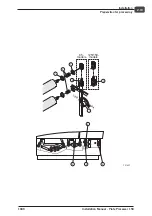
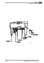
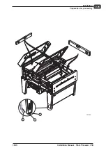


Changing from 3W+N+PE to 3W+PE
•
Locate the GFCI
(F10)
–
Move the yellow wire from terminal 3 to
terminal 1 and mount it together with the
red wire.
–
Move the brown wire from terminal 5 to
terminal 3 and mount it together with the
orange wire from terminal N
(a)
.
–
Move the blue and the black wires from
terminal N
(a)
to terminal 5.
–
Mount jumper (see spare parts box) from
terminal 4 to terminal N.
–
Locate terminal strip X7.
–
Connect the power supply cable to
terminal L1, L2, L3, and PE.
"
For an installation without neutral wire,
fuses F33, F34, F35, F36, F 37 and F38 must
be installed. Jumpers x69, x70,c x71, x72x
x73 and x74 located on the fuse PCB must be removed.
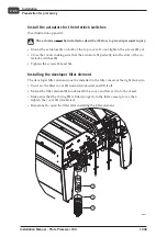
Modification to transformer
•
If the processor is to be installed in countries
where the voltage is other than 230V,
the following modification must be made to
transformer T1
and
T2
:
•
Turn the main switch to "0/OFF".
•
Remove the left side panel from the processor.
•
Remove the screw securing the lid of the
electronics cabinet and open it by pulling
outwards with a firm grip.
•
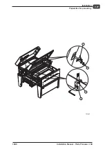
Measure AC supply as follows:
–
Line to line
if supply is from 3W+PE or
2W+PE
–
Line to neutral
if supply is from
3W+N+PE, and set tapping of the
transformer as follows:
- 180V - 220V AC to 200V Tap,
- 207V - 253V AC to 230V Tap.
•
200V -230V is the nominal voltage and 180V -
220V (207V - 253V) is the range where normal
operation is obtained.
$
If AC supply at the installation site is in the range of 207 - 220V, we
recommend using the 200V tapping.
Installation Manual - Plate Processor 150
1049
2-14
Installation
Electrical specifications
2
1
2
3
4
X7
F10
1
RED
YELLOW
BROWN
BLUE
ORANGE
BLACK
4
3
6
5
10
12
8
6
4
2
T
L1
L2
POWER SUPPLY CONNECTION
FOR 3W+N+PE (standard)
L3
N
PE
RED
YELLOW
BROWN
BLUE
Main switch
To X3
on fuse PCB
N
N
T2612
b
a
X57
T1
T2
T31689


