


12
221954D
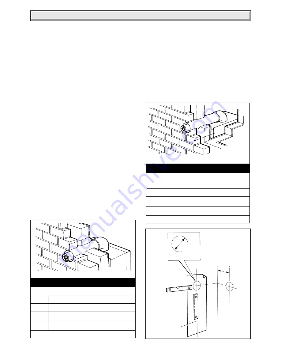
4.4. Rear and Side Flue Application
Take the template from the boiler pack and position it on the
wall, making sure that the minimum clearances are maintained,
see diagram 1.3.
For a rear flue mark the position of the flue as diagram 4.3.
For a side flue, extend the centre line horizontally left or right to
the corner of the adjacent surface where the flue is required to
exit. Mark the position of the centre of the flue and boiler, then
remove template as diagram 4.3.
4.5 Flue Hole Cutting
Having marked out the flue centre cut a hole for the flue using,
preferably, with a core drill.
Diagram 4.3
120 mm
MINIMUM
HOLE
127mm
SIDE FLUE
FLUE/BOILER
CENTRE LINE
4277
4.1 Unpacking
Open the carton, check the items supplied against the boiler
pack contents list on the flap.
4.2 Flue Position and Length
There are various flue systems to choose from, as follows:
Standard Flue Pack - Pt.No. 230515
A Flue Bend Kit up to 2 metres and a Vertical Flue Kit up to 2
metres plus vertical terminal can be supplied, see Glow-worm
“Flue Options Guide” for configurations available.
45
0
Flue Bend Pack - Pt.No. 448696
90
0
Flue Bend Pack - Pt.No. 448695
Vertical Flue Kit No. - 2000448455
Determine flue applications, length and terminal position before
starting.
Refer to diagram 4.1 or 4.2.
NOTE:
If a longer flue duct is required DO NOT extend the
telescopic flue beyond its maximum length.
A 1, 2 or 3metre flue system and terminal MUST be used, for
the 100FF and 1 or 2 metre only for the 120FF.
NOTE:
If required, an optional Wall Liner Kit, part No.452481,
is available, complete with fixing instructions.
4.3 Flue Preparation
All flue assemblies are designed for internal installation (optional
wall liner is required), given that there is sufficient clearances
opposite to the flue for the installation of the flue.
If there is insufficient clearance the flue can be installed from
outside.
For a wall thickness up to 300mm, provided that there is
sufficient space and the optional wall liner kit is used the flue can
be fully installed from the inside.
For a wall thickness of over 300mm the external flue hole will
need to be made good from the outside. This applies also if you
use the flue kit without the optional kit, irrespective of wall
thickness.
Diagram 4.2
7370
Standard Flue terminal illustrated.
'S'
Distance S = External wall face to boiler case
STD.
81mm to 439mm
1M
81mm to 830mm
2M
81mm to 1830mm
*3M
81mm to 2830mm *100FF ONLY
Diagram 4.1
7368
Standard Flue terminal illustrated.
REAR FLUE LENGTHS
Distance R = Wall thickness
STD.
75mm to 519mm
1M
75mm to 928mm
2M
75mm to 1928mm
*3M
75mm to 2928mm *100FF ONLY
'R'
4 Flue and Appliance Preparation
SIDE FLUE LENGTHS