


7 Start-up
18
Installation and maintenance instructions ENERGY 0020177746_03
◁
The pressure value flashes in the display until a
pressure of 0.05 MPa (0.5 bar) or higher has been
reached.
7.6
Switching on the product
▶
Switch on the product via the main switch installed on-
site.
7.7
Filling and purging the heating installation
Preliminary work
▶
Flush the heating installation through.
1
1
1.
Check the silicone hose connection
(1)
between the
pump's automatic air vent and the hydraulic console.
2.
Fill with water until the required filling pressure is
reached.
–
Recommended filling pressure: 1 … 1.5 bar
◁
The heating and hot water functions cannot be activ-
ated.
◁
The pressure value flashes in the display until a
pressure of 0.05 MPa (0.5 bar) or higher has been
reached.
◁
An automatic air vent function is activated if the
pressure exceeds 0.05 MPa (0.5 bar) for longer than
15 seconds.
3.
Purge each radiator until the water escapes normally,
and then retighten the system's purging valves.
4.
Check whether all connections are leak-tight.
Conditions
: If the noise persists in the boiler
▶
Purge the product again by activating check programme
(P.07)
and then
(P.06)
.
Check programmes
–
Overview (
→
Page 30)
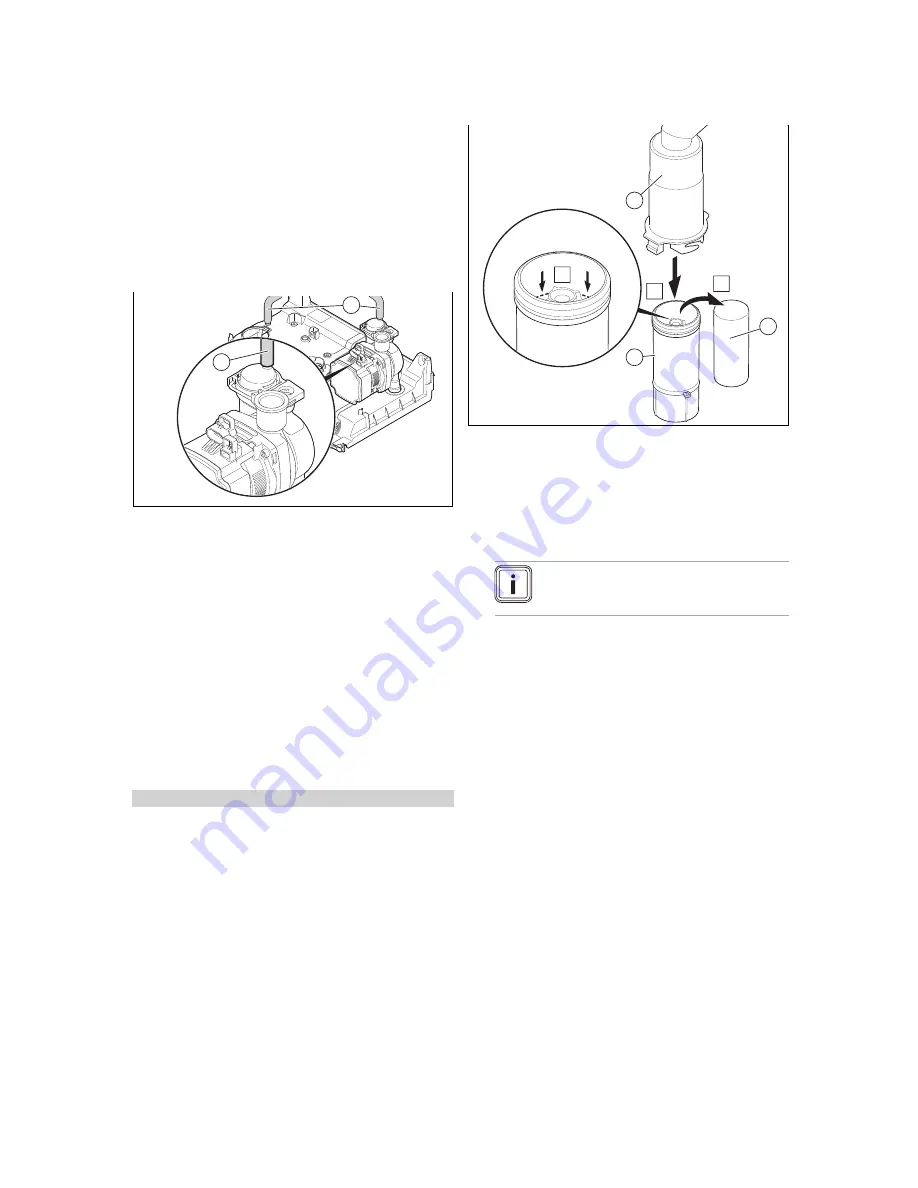
7.8
Filling the condensate siphon
C
2
3
1
A
B
1.
Unclip the lower section of the siphon
(1)
from the up-
per section of the siphon
(2)
.
2.
Remove the float
(3)
.
3.
Fill the lower section of the siphon with water up to 10
mm below the upper edge of the condensate drain pipe-
work.
4.
Re-insert the float
(3)
.
Note
Check that the float is present in the con-
densate siphon.
5.
Clip the lower section of the siphon
(1)
into the upper
section of the siphon
(2)
.
7.9
Filling the hot water circuit
1.
Open the water tap to fill the hot water circuit.
2.
Close the water tap once the appropriate volume of
water has flowed out.
◁
The hot water circuit is filled.
3.
Check all connections and the entire system for leak-
tightness.
7.10
Checking and adjusting the gas settings
Only a qualified competent person is authorised to imple-
ment the settings on the gas valve assembly.
Each destroyed tamper-proof seal must be replaced.
The CO
₂
adjusting screw must be sealed.
Never modify the factory setting of the gas pressure regu-
lator of the gas valve assembly.
7.10.1 Checking the gas flow rate
The gas flow rate has been set during production and does
not require adjustment. With the front casing fitted check the
gas flow rate of the boiler as follows:
▶
Start up the product with the check programme
P.01
.
Summary of Contents for ENERGY 25c
Page 1: ...Installation and main tenance instructions ENERGY 25c 30c 35c GB IE...
Page 50: ......
Page 51: ......