Glow-worm Economy Plus 30 B Instructions For Use Installation And Servicing Download Page 8

Supplied By www.heating spares.co  Tel. 0161 620 6677

8

221481C

3 Water Systems

Notes:

PUMP

The pump should be fitted in the flow pipework from the boiler,
with valves each side, integral if possible, it should produce a
temperature difference across the boiler of 11

o

C (20

o

F).

Flow rates should be,

11.5 Litre/min (2.5gal/min)

See diagram 3.1 for pressure loss across the boiler.

High resistance microbore systems may require a higher duty
pump.

BYPASS

The flow through the boiler must not be allowed to fall below,
7.8  Litre/min (1.7gal/min) whilst the burner is alight.

A bypass must be fitted.

3.1 Open Vented Systems

Water system

For an open vented system the boiler must be supplied from an
unrestricted water supply taken from a feed and expansion
tank, situated at a maximum height of 27.5metres (90ft) above
the boiler.

The cold feed supply must be 15mm minimum size.

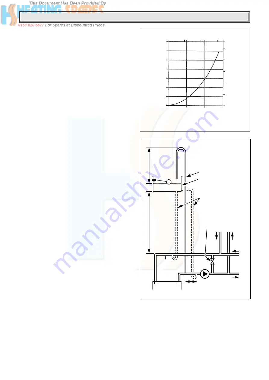
It is important that the relative positions of the pump, cold feed
and open vent are as shown in diagram 3.2.

3.2 Cylinder

SINGLE FEED SELF PRIMING CYLINDERS ARE NOT
RECOMMENDED.

The hot water cylinder must be a double feed fully indirect type.

3.3 Inhibitor

Attention is drawn to the current issue of BS5449 and BS7593
on the use of inhibitors in central heating systems.

If an inhibitor is to be used, contact a manufacturer for their
recommendations for the best product to use.

When fitting the boiler into an existing system take special care
to drain the entire system including the radiators, then thoroughly
cleaning out before fitting the boiler whether or not adding an
inhibitor.

Sealed Water Systems

The installation should comply with the appropriate requirements
of the current issue of BS4814, BS5449 BS6759 BS6798 and
BS7074 Part 1 and 2.

See diagram 3.3 for a suggested layout.

3.4 Safety Valve

A safety valve must be fitted to a sealed water system.

It shall be preset, nonadjustable with a lift pressure of 3bar,
incorporating seating of a resilient material, a test device and a
connection for drain.

The drain from the safety valve must be routed clear of any
electrical fittings and positioned so that any discharge can be
seen.

PRESSURE LOSS OF BOILER
ECONOMY

Diagram 3.1

2761

LITRES / MINUTE

GALLONS / MINUTE

(m head of water)

WATER PRESSURE LOSS

0

0.1

0.2

0.3

0.4

0.5

0.6

0.7

0

5

10

15

0

5

10

15

20

25

1

2

3

(m head of water)

WATER PRESSURE LOSS

Diagram 3.2

Open (vented) system.
Recommended
relationship between
pump, cold feed and
vent.

22 mm (MIN) VENT

FEED AND
EXPANSION
CISTERN

15mm (MINIMUM)
COLD FEED

15mm (MINIMUM)
BY-PASS WITH
LOCKSHIELD VALVE

450mm
MIN.
HEIGHT

1150mm
MIN.

150
mm
MIN.

BOILER

PUMP

150mm
MAX

FLOW

RET.

ALTERNATIVE

PREFERRED

RET.

CYLINDER

FLOW

HEATING

0392

Summary of Contents for Economy Plus 30 B

Page 1: ...telephoning the Heatcall Customer Service number 01773 828100 Our Guarantee gives you peace of mind plus valuable protection against breakdown by covering the cost of Guarantee Registration Balanced F...

Page 2: ...ctioncertifiedby Notified body 0086 The CE mark on this appliance shows compliance with 1 Directive 90 396 EEC on the approximation of the laws of the Member States relating to appliances burning gase...

Page 3: ...petent person To obtain service please call your installer or Heatcall Glow worm s own service organisation using the telephone number on the case tray Please be advised that the Benchmark logbook sho...

Page 4: ...hat the electrical supply to the boiler is switched off Identify the controls by reference to diagram 2 Turn thermostat knob A fully anti clockwise to the OFF position Push and keep in gas control kno...

Page 5: ...bstancesHazardous toHealth TheElectricityatWorkRegulationsandanyapplicable local regulations Detailed recommendations are contained in the current issue of the following British Standards and Codes of...

Page 6: ...iler is delivered in one pack The other pack contains the balanced flue terminal assembly and accessories Refer to Section 2 to check that the flue terminal assembly supplied is suitable kW Btu h kW B...

Page 7: ...purpose An existing cupboard or compartment modified for the purpose may be used Details of essential features of cupboard or compartment design are given in the current issue of BS6798 The doorway op...

Page 8: ...tral heating systems If an inhibitor is to be used contact a manufacturer for their recommendations for the best product to use When fitting the boiler into an existing system take special care todrai...

Page 9: ...ial design pressure requires a larger volume expansion vessel Guidance on vessel sizing is also given in the current issue of BS5449 and BS7074 Part 1 The charge pressure must not be less than the sta...

Page 10: ...YSTEM HEATING SYSTEM TEMPORARY HOSE HOSE UNIONS SERVICING VALVE SUPPLY PIPE SUPPLY STOP VALVE DOUBLE CHECK VALVE ASSEMBLY HEATING SYSTEM SERVICING VALVE SUPPLY STOP VALVE SUPPLY PIPE HOSE UNIONS DOUBL...

Page 11: ...URING SCREWS BOTTOM 4 2 Appliance Preparation Remove the controls cover by pulling it forwards and off Remove the outer case by undoing the screw at the bottom and unhooking at the top Remove the inne...

Page 12: ...t Refit the two screws through the duct flange but do not over tighten Replace flue hood securing angle tie rods and wing nuts Refit the inner cover and secure with the screws previously removed 5 2 I...

Page 13: ...STRAIN RELIEF GROMMET EARTH POST RETAINING STRAP SECURING SCREWS TERMINAL STRIP 2420 FASTENER Warning The boiler must be earthed and have a permanent mains supply 7 1 Electrical Connection To remove t...

Page 14: ...2416 7 Electrical Wiring Diagram 7 2 WIRING DIAGRAM FOR CONTROL BOX 2419 BROWN BLUE GRN YELLOW BROWN BLUE 240 50Hz PERMANENT MAINS SUPPLY FUSED AT 3A L N L N CIRCULATION PUMP CHASSIS EARTH POST GRN Y...

Page 15: ...ake sure that the pilot is alight and stable view through windows G Set the boiler thermostat knob A between 1 and 5 and checkthattheburnerlightssmoothly Checkthegasconnections for gas soundness with...

Page 16: ...two screws and washers securing the pilot burner and shield to the main burner see diagram 10 2 Pull the pilot assembly forward enough to allow the main burner to be freed from the injector Raise the...

Page 17: ...uple nut more than a quarter turn beyond finger tight It will be necessary to purge the pipework and valve before relighting refer to Commissioning 10 8 Electrical Control Box Remove controls cover an...

Page 18: ...ignition lead when replacing ensure that the clear end is fitted to the electrode 10 11 Thermostat Gain access as Section 10 3 Remove and support the control box as Section 10 9 Remove the control kno...

Page 19: ...ation Check venting of system as air bubbles can remain suspended in the water if system is not well vented Check that flow rate is correct Check that pump is correct size and is correctly adjusted By...

Page 20: ...ve either at A or C Renew where faulty Faulty thermocouple renew NO YES Thermocouple and boiler overheat circuit Satisfactory YES Test continuity of thermocouple between inner connection point D and p...

Page 21: ...40V between L and N on gas valve Faulty gas valve renew Faulty gas valve harness renew Turn ON thermostat Does main burner light Turn ON thermostat With appliance cold Is there 240V between 7 and N Tu...

Page 22: ...Calling for Duty does pump stop when the appliance has cooled down CONTROLS IN ORDER Faulty Cable PURPLE between thermostat and terminal block repair or renew Faulty pump inform customer Faulty thermo...

Page 23: ...ACTORY Does pilot flame envelop thermocouple Check aeration If necessary clean pilot Rectify blockage in pilot injector Adjust pilot throttle Check thermocouple circuit using fault finding chart On pr...

Page 24: ...verheat cutoff assembly 313 064 5 800015 Gas valve assembly incs 14 313 067 6 900000 Thermocouple 381 651 7 203415 Pilot burner incs 12 394 161 8 202600 Electrode 384 149 9 416144 Thermostat control k...

Reviews: