


3307740 PICMG 1.3 CPU Card
Page 98
Step 2:
Inspect the CPU socket.
Make sure there are no bent pins and make sure the
socket contacts are free of foreign material. If any debris is found, remove it with
compressed air.
Step 3:
Correctly Orientate the CPU
. Make sure the IHS (integrated heat sink) side is
facing upwards.
Step 4:
Correctly position the CPU.
Match the Pin 1 mark with the cut edge on the
CPU socket. See
Figure 5-1
.
Step 5:
Align the CPU pins.
Carefully align the CPU pins with the holes in the CPU
socket.
Step 6:
Insert the CPU.
Gently insert the CPU into the socket. If the CPU pins are
properly aligned, the CPU should slide into the CPU socket smoothly.
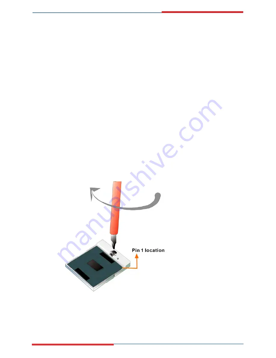
Step 7:
Lock the retention screw.
Rotate the retention screw into the locked position.
See
Figure 5-2
.
Figure 5-2: Lock the CPU Socket Retention Screw
Summary of Contents for 3307740
Page 1: ...User s Manual PICMG 1 3 3307740 Version 1 0 ...
Page 3: ...Page i Revision Date Version Changes 2007 03 23 1 00 Initial release ...
Page 15: ...3307740 PICMG 1 3 CPU Card Page 19 Introduction Chapter 1 ...
Page 21: ...3307740 PICMG 1 3 CPU Card Page 25 Detailed Specifications Chapter 2 ...
Page 48: ...3307740 PICMG 1 3 CPU Card Page 52 Unpacking Chapter 3 ...
Page 54: ...3307740 PICMG 1 3 CPU Card Page 58 Connector Pinouts Chapter 4 ...
Page 61: ...3307740 PICMG 1 3 CPU Card Page 65 Figure 4 4 CF Card Socket Location ...
Page 87: ...3307740 PICMG 1 3 CPU Card Page 91 THIS PAGE IS INTENTIONALLY LEFT BLANK ...
Page 88: ...3307740 PICMG 1 3 CPU Card Page 92 Installation Chapter 5 ...
Page 97: ...3307740 PICMG 1 3 CPU Card Page 101 Figure 5 4 CF Card Installation ...
Page 121: ...3307740 PICMG 1 3 CPU Card Page 125 DIO Interface Appendix A ...
Page 124: ...3307740 PICMG 1 3 CPU Card Page 128 THIS PAGE IS INTENTIONALLY LEFT BLANK ...
Page 125: ...3307740 PICMG 1 3 CPU Card Page 129 Watchdog Timer Appendix B ...
Page 127: ...3307740 PICMG 1 3 CPU Card Page 131 ...
Page 129: ...3307740 PICMG 1 3 CPU Card Page 133 Address Mapping Appendix C ...


