


If the size on the diagram A is changed, then the opening angle will be changed (90
– 110 degrees)
Please change the size according to following rule.
1. 132<A<145,132<b<145 mm
2. If the opening angle is more than 90 degrees, then A+B<C
3. The smaller value A and B, the faster the gate works.
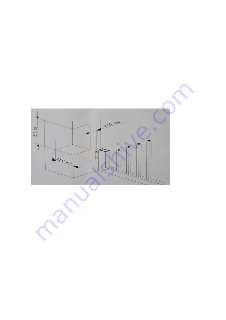
If the size of the gate post or hinges not the same as A, please dig according
to following diagram.
Installation procedure:
If the Pillar is Iron, weld supporting clamps. If Concrete use Anchor Bolts.
1. Release the GEAR MOTOR ARM. CLOSE both gates.
2. Extend the Lever Arm fully outwards, by rotating the Arm Extension.
3. Rotate the Arm Extension one turn clockwise.
4. Mount the Base bracket to the pilar, corresponds to horizontal section of the gate.
using water level. Fix with anchor bolt. Attach Tail Plate with 2 bolts.
5. Screw the Motor Arm to this Tail Plate. Then spot weld the END Clamp to the
gate. See that the Motor arm is horizontal.
5. Ensure the gate can be opened and closed fully.
6. Weld the End Clamp strong. And install second motor like this.
7. CLOSE both gates.


