


When mounted at heights above 3 metres there could be a
significant reduction in the range of detection and the target
will have to move a greater distance within the field of view
before an alarm is generated.
Figure 12 shows the pattern for the maximum range in the
optimum position (see Figure 10). Masking the top section
of the lens reduces the range to 20m.
Figure 13 shows the pattern for the minimum range. In this
case masking the top section of the lens reduces the range
to 6 meters.
Figures 14 and 8 illustrates alignment recommendations for
when the detector is mounted close to a wall.
The alignment shown in Figure 14 is not recommended. If
the detector module is orientated at an angle of 90° to the
perimeter, the mounting wall may cut off short and medium
range beams.
The long range beam will still detect an intruder, however
the wall can cause false alarms when heated by sunlight.
Figure 8 shows the recommended alignment. The detector
module is orientated at a 55° angle to the perimeter. As a
result, short and medium range beams are parallel to the
perimeter, but the detection range along the perimeter is
reduced to 25 metres.
PROGRAMMING
There are 2 different ways of programming the detection
range, pulse count and LED setting.
1. Using the programming button, programming LED and
programming chart below.
2. Via the web based interface. The user can individually
program a number of configurable settings, as
illustrated in the programming chart.
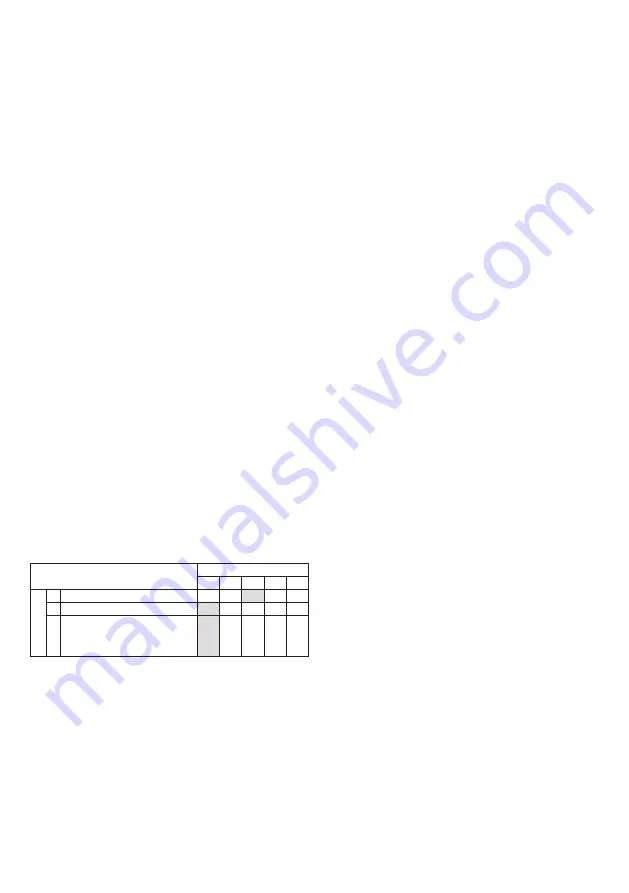
USING PROGRAMMING BUTTON
Programming Chart
SETTING
1
2
3
4
5
O
P
T
I
O
N
S
1
RANGE (m)
8
15
20
25
30
2
Pulse Count
1
2
3
3
LED
Off
On
To change any of the D-TECT 3 IP settings:
1. Press the program button, as shown in figure 4, for
the number of the Option to be changed, i.e. once for
range, twice for pulse count, three times for LED.
2. Wait until the blue LED indicator goes off (typically four
seconds).
3. The indicator will then flash out the existing settings.
4. To change the settings for that option, press the pro-
gram button the number of times for the required new
setting.
5. The indicator blinks twice and the changes are stored in
the D-TECT 3 IP’s non volatile memory.
Example: To change the LED setting from OFF to ON:
1. Press the program button three times.
2. Wait until the blue LED indicator goes off (typically four
seconds).
3. The indicator will then flash once, indicating the current
LED setting is OFF.
4. Press the program button twice to change the setting
to ON.
5. The indicator blinks twice and the changes are stored in
the D-TECT 3 IP ’s non-volatile memory.
PROGRAMMING OPTIONS DEFINITIONS
Pulse Count
This is the number of times the unit has to detect on both of
its sensors before signalling an output.
LED
LED Off – LED disabled.
LED On – LED signals a detection.
Relay outputs
Output 1 and output 2
These are magnetically immune volt free relay contacts
used to trigger alarm inputs on connected equipment.
The contacts are rated at a maximum of 24V AC/DC @
50mA.
The contact operating timer can be adjusted in the web
based user interface.
WALK TEST
In walk test mode, the detection LED option is set to ON,
and the pulse count option is set to 1.
1. The detection LED lights each time the D-TECT 3 IP
detects your presence
2. To enter the walk test mode, press the programming
button once. The detection LED is enabled and pulse
count 1 is automatically selected. Alternatively, the
walk test mode can be entered via the web based user
interface. The unit can then be aligned.
3. The test mode ends automatically five minutes after the
last activation. Alternatively, press the program button
three times, to cancel the walk test mode.
Note: When you conduct a walk test, make sure that
the front cover is in place. Do not conduct walk tests
with the cover removed.
The range of the detector increases without the protective
front cover. Therefore the front cover must be fitted to
establish the correct beam pattern. Use the programming
chart to adjust the range as necessary. Pan and tilt the lens
module over the field of view to obtain the correct coverage
area.
Microwave Frequencies
GJD260: D-TECT 3 IP MOTION DETECTOR 10.587GHz
GJD261: D-TECT 3 IP MOTION DETECTOR 10.525GHz
GJD262: D-TECT 3 IP MOTION DETECTOR 9.9GHz
10 dBm EIRP


