background image

8-

m

m

NA

sp

ee

d

4

2

3

1

4

4

sp

ee

d

3

3

3

4

sp

ee

d

sp

ee

d

2

re

d

2

1

re

d

1

2

1 10 4 3

4

3

1

2

1

0

1

2

3

4

10

L3
L2
L1
PE

PE
L1 U
L2 V
L3 W

15

Swiss Lifting Solutions

2.2.2  Brake system

The brake must be able to hold the nominal load in power free mode without any problems. For chain hoists with two brakes, the functio-

nality of the two brakes must be checked during the system acceptance test. The first brake is on the DC side, the second brake on the AC 

side and thereby switches with a slight delay.

The functional testing of the brake system is carried out under nominal load:

First brake:

Release the mounting screws of the second brake. The rotor of this brake now rotates freely. The function of the second brake is discon-

nected. Raise and lower: The first brake must be capable of braking and hold the nominal load. Tighten the mounting screws again after 

the function test.

Second brake:

Electrical Method:

The first brake is released from + and - terminals and activated by a non-controlled current source (directly from L1 and L2). To activate a 

rectifier must be switched between. Thus, the first brake is disconnected and the second brake can be tested by lifting and lowering the 

load. Lifting and lowering with unloaded first brake: The second brake must be capable of braking and hold the nominal load. After the 

function test reconnect the first brake to the ter and -.

Mechanical method:

With a tool, the pressure ring of the first brake is pressed to the solenoid, so that the rotor of the brake can rotate freely. The function of 

the first brake is disconnected. Lifting and lowering with unloaded first brake: The second brake must be capable of braking and hold the 

nominal load.

Figure 2-4 

Figure 2-5

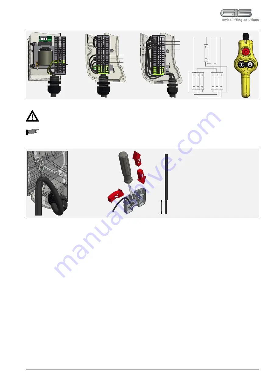
•  Checking direction of rotation: If the directions of movement do not match the button symbols of the control switch,  

  the supply line wires L1 and L2 must be transposed.

•  In the single-phase version, inching operations can cause malfunctions.

Open the terminal used in accordance with figure 2-5.

Figure 2-1 

Figure 2-2 

Figure 2-3


Summary of Contents for LP 1000

Page 1: ...01 20 Translation 9500 9003 1 TRANSLATION OF THE ORIGINAL INSTRUCTION MANUAL ELECTRIC CHAIN HOIST LP ...

Page 2: ......

Page 3: ...ons 10 1 2 General description 12 2 Start up 13 2 1 Transport and assembly 13 2 2 Connections 14 2 2 1 Electrical connections 14 2 2 2 Brake system 15 2 2 3 Load chain 16 2 2 4 Limit switch 18 2 2 5 Chain container 19 3 Care and maintenance 20 3 1 General guidelines for maintenance and repair 20 3 2 Care and maintenance 21 3 2 1 Care overview 21 3 2 2 Maintenance overview 21 3 2 3 Brake system 21 ...

Page 4: ...sse 50 tel gis ag ch CH 6247 Schötz www gis ag ch The correct order numbers for original spare parts can be obtained from the corresponding spare parts list Please ensure that you have the following data on your electric chain hoist to hand This will enable the correct spare parts to be supplied without delay Electric chain hoist type Serial number Year of manufacture Load capacity Spare parts Ord...

Page 5: ...operator or their representative is responsible for supervising operating personnel and ensuring they are aware of the hazards and safety implications of working with the electric chain hoist The manufacturer reserves the right to make technical changes to the product or changes to these instructions and assumes no liability for the completeness and up to dateness of these instructions The origina...

Page 6: ...be secured against unauthorised and unintentional use Refrain from hazardous procedures See also operational parameters chapter 0 6 Cleaning service repair maintenance refitting Use working platforms provided for assembly work at high level Do not use machine parts for this purpose Check electrical cables for damage or wear Ensure any oils or other agents used are collected and disposed of safely ...

Page 7: ...oist motor to the measuring device Measurement of SPL per DIN 45 635 The sound pressure level was measured a During operation of electric chain hoists on factory site b During open air operation of electric chain hoists Physical injury Death from electrical shock injury and burns through contact faulty insulation faulty maintenance or repair work short circuit Causes contact with touching or stand...

Page 8: ... 2 and shall not be used for holding or moving loads above people without employing additional protective measures The electric chain hoists of the LP types are lifting equipment for various loads They can be installed as stationary or mobile units while a lateral oscillation must be ensured The electric chain hoists are manufactured in accordance with the latest technical developments and recogni...

Page 9: ...er 0 3 With persons present under the load Use D8 D8 with secondary safety device D8 PLUS C1 Assembly and dismantling set up mode inadmissible inadmissible inadmissible permissible Holding loads inadmissible permissible permissible permissible Scenic movement inadmissible inadmissible inadmissible permissible Table 0 2 Operating conditions D8 PLUS electric chain hoist In the context of this qualit...

Page 10: ...bout general overhaul see chapter 4 There is different coefficient data for the classifications that must be adhered to in operation The travel trolley must have at least the same lifting capacity as the electric chain hoist The classification of the electric chain hoist can be found on the data plate 1 1 Operating conditions The LP series includes the following models LPM LPML LP LPL 1 Descriptio...

Page 11: ...ist Before initial start up of the electric chain hoist it is necessary to ascertain which of the load types in table 1 1 applies to the operation of the electric chain hoist Assignment to a load type or a load spectrum Q applies for the whole service life of the equipment and may not be altered for operational safety reasons Classification according to DIN EN 14492 2 ISO 4301 1 A3 M3 A4 M4 A5 M5 ...

Page 12: ...lectric chain hoists of the LP series are suitable for direct control The high tensile profile steel chain corresponds to grade DAT 8SS per DIN EN 818 7 The chain wheel is hardened The load hook which complies with DIN 15401 DIN EN 13001 is fitted with a safety catch The 3 stage enclosed spur gears are generally helical The gears are mounted on roller bearings and run with grease lubrication Addit...

Page 13: ...fects of the weather 2 1 Transport and assembly Mechanical adjustments may only be performed by authorised specialists Operating staff must carefully read the instruction manual of the electric chain hoist before initial start up and carry out all the checks The device shall be put back into operation only after operational safety has been established Unauthorised persons may not operate the devic...

Page 14: ...upply must be provided by the customer A 4 wire cable with a PE protective conductor is needed as a supply line for three phase versi ons A 3 wire cable with a protective conductor is adequate for single phase version The length and cross section must be appropriate for the power consumption of the electric chain hoist The wiring diagram is located in the lid of the electric chain hoist In D8 PLUS...

Page 15: ...e first brake is released from and terminals and activated by a non controlled current source directly from L1 and L2 To activate a rectifier must be switched between Thus the first brake is disconnected and the second brake can be tested by lifting and lowering the load Lifting and lowering with unloaded first brake The second brake must be capable of braking and hold the nominal load After the f...

Page 16: ...53 mm LP 2500 87 mm Grease the bearings thoroughly load hook Figure 2 6 2 2 3 Load chain Only use original chains Welding seam of the chain links must face inward on the chain wheel see figure 2 6 When used as a climbing hoist make sure that the entry and the run out of the chain is not prevented by chain clusters The geared limit switch must be mechanically deactivated for pulling in the chain se...

Page 17: ... with figure 2 14 Connect load side chain end with the chain holder 3 and fasten into the guide rail of the housing Secure the chain holder with screw 4 and spring washer 5 Note correct arrangement of suspension mass k2 see figure 2 15 LP 2500 130 mm No longitudinal twisting of the chain see figure 2 16 Grease the bearings thoroughly deflection roller load hook Figure 2 10 Figure 2 11 Figure 2 12 ...

Page 18: ... therefore only possible if the emergency limit switch is bridged LP 2500 Transmission Colour 1 fall lifting height m 2 falls lifting height m i 1 1 black 42 21 i 1 1 5 red 63 31 5 i 1 3 yellow 126 63 i 1 6 blue 252 126 LP 1600 Transmission Colour 1 fall lifting height m 2 falls lifting height m i 1 1 black 34 i 1 1 5 red 51 i 1 3 yellow 102 i 1 6 blue 204 LP 1000 Transmission Colour 1 fall liftin...

Page 19: ...d allow the chain to run in Vertically mounted chain hoists LPM LPML 250 see figure 2 19 LP LPL 500 see figure 2 20 LP 1000 see figure 2 21 LP 1600 2500 see figure 2 22 or climbing hoists LPM LPML 250 see figure 2 23 LP LPL 500 see figure 2 24 LP 1000 see figure 2 25 LP 1600 2500 see figure 2 26 Chain container must hang freely Badly lubricated chains will occupy more volume in a chain container W...

Page 20: ...t discolouration and arc spots Used operating materials oil grease etc should be safely collected and disposed of in an environmentally friendly manner Operating failures in electric chain hoists affecting the safe operation of the device should be remedied immediately Maintenance and repair work on the electric chain hoist may only be carried out by qualified and trained personnel If the operator...

Page 21: ... Task Remark 1 Load chain x x Oil Measure wear see chapter 2 2 3 3 2 4 2 Brake system x x Function check with load see chapter 3 2 3 3 Electrical equipment x Function check 4 Fixing screws on suspension parts and load hook with accessories x Check for cracks Check screw torque see chapter 3 2 9 5 Limit switch x Check switching elements see chapter 2 2 4 6 Slipping clutch x Function check see chapt...

Page 22: ...er dm d1 d2 2 dm min 0 9 x d mm 3 4 3 7 4 7 5 1 6 7 Table 3 4 Load chain wear values 3 2 4 Load chain The load chain should be periodically checked for abrasion The check is based on three measurements see permissible wear values table 3 4 and table 3 5 and measuring points figure 3 2 The chain should be replaced when the measurements no longer comply with those defined in the table The chain whee...

Page 23: ...e values for screws of strength class 8 8 per DIN ISO 898 3 2 8 Slipping clutch The slipping clutch is set to 125 at the factory and reliably prevents overloading of the chain hoist the power limiting factor per DIN EN 14492 2 is ΦDAL 1 6 In the case of the two lowest lifting capacities in tables 5 1 to 5 5 the factor is 2 The resultant forces arising from the adjustment of the slipping clutch mus...

Page 24: ...ff are to be recorded in the inspection pass 4 1 Determining the actual operating time Classification according to DIN EN 14492 2 ISO 4301 1 A3 M3 A4 M4 A5 M5 A6 M6 Load spectrum Number of load cycles throughout the whole service life Q2 0 50 250 000 500 000 1 000 000 2 000 000 Q3 0 63 125 000 250 000 500 000 1 000 000 Q4 0 80 63 000 125 000 250 000 500 000 Q5 1 00 31 500 63 000 125 000 250 000 Th...

Page 25: ... the equipment to continue operating safely for a further period of time Components must be checked or replaced in ac cordance with table 4 2 The checking and release for the further use must be done by a specialist company authorised by the manufactu rer or by the manufacturer themselves The inspector determines What new theoretical full load cycles are possible The max period until the next gene...

Page 26: ... d 40 ED A5 M5 60 C d 40 ED A5 M5 60 C d 40 ED A5 M5 60 C d 40 ED Lifting speed 50 Hz Lifting speed 60 Hz Motor type Number of falls Dead weight Main fuse 400 V slow blow Series Load capacity kg m min m min kg A Chain safety 5 1 6 4 1 8 1 10 1 12 5 1 16 1 LPM 250 1NL D8 400 320 250 200 160 100 4 4 8 71 A 4 1 12 6 LPML 250 1NL D8 500 4 4 8 71 A 4 1 12 6 LP 500 1NF D8 LP 500 1NL D8 LP 500 1N D8 800 ...

Page 27: ...0 630 4 4 8 90 B 4 1 46 16 Chain safety 10 1 12 5 1 16 1 20 1 25 1 32 1 LPM 250 1N D8 1Ph 125 100 8 9 6 71 A 4 1 14 10 LP 500 1N D8 1Ph 250 200 160 125 8 9 6 80 A 4 1 22 10 LP 1000 1N D8 1Ph 500 400 8 9 6 90 B 4 1 46 16 Table 5 4 Technical data LP D8 single phase version must be operated with a frequency inverter DIN EN ISO classification A3 M3 15 C d 25 ED A4 M4 30 C d 30 ED A5 M5 60 C d 40 ED A5...

Page 28: ...s and start up current 3 x 400 V 50 Hz 3 x 230 V 50 Hz kW 1 min IN 380 A IN 415 A Imax A IA IN 415 cos phiN IN 220 A IN 240 A Imax A IA IN 240 cos phiN LPM 250 71 A 4 4 0 25 1385 1 6 2 0 2 6 1 65 0 55 2 8 3 4 4 4 1 65 0 55 LPML 250 71 A 4 4 0 38 1385 1 8 2 2 2 8 1 65 0 55 3 0 3 6 4 4 1 65 0 55 LP 500 80 B 8 2 8 0 18 665 1 4 1 9 2 2 1 45 0 51 2 4 3 1 3 5 1 45 0 51 2 0 72 2745 2 4 3 4 3 7 2 75 0 77 ...

Page 29: ...phiN LPM 250 71 A 4 4 0 25 1385 5 7 5 9 1 65 0 55 3 0 3 2 1 95 0 55 LP 500 80 A 4 4 0 55 1420 10 6 11 4 1 95 0 68 4 5 4 9 2 45 0 68 LP 1000 90 B 4 4 1 50 1420 13 0 17 0 1 95 0 76 6 0 7 5 2 45 0 76 Table 5 9 Electrical parameters LP single phase version Series Motor type No of poles PN nN min max currents and start up current 3 x 208 230 460 V 60 Hz kW 1 min IN 208 A IN 460 A Imax A IA IN 460 cos p...

Page 30: ...9 1 Safety related parts of control systems Part 1 General principles for design DIN EN 14492 2 Cranes power driven winches and hoists Part 2 Power driven hoists DIN EN 60204 32 Electrical equipment of machines Part 32 Requirements for hoisting machines Standards and technical specifications applied FEM 9 751 Power driven lifting device series safety FEM 9 755 Measures for achieving safe operating...

Page 31: ...818 7 Chains for lifting purposes Part 7 Grade T DIN EN ISO 13849 1 Safety related parts of control systems Part 1 General principles for design DIN EN 14492 2 Cranes power driven winches and hoists Part 2 Power driven hoists DIN EN 60204 32 Electrical equipment of machines Part 32 Requirements for hoisting machines Standards and technical specifications applied FEM 9 751 Power driven lifting devi...

Page 32: ......

Reviews:

Related manuals for LP 1000