2
WIRING CONNECTIONS
NOTICE:
Clamp the power cable to prevent strain on the
terminal screws.
Refer to motor wiring diagram on pump motor for proper motor
wiring connection.
1. Install, ground, wire and maintain this pump in
compliance with the National Electrical Code (NEC) or the
Canadian Electrical Code (CEC) and with all local codes
and ordinances that apply. Consult your local building
inspector for local information.
2. Make sure that the voltage, frequency and phase (single
phase or three phase) of the power supply agree with that
stamped on the motor nameplate. If in doubt, check with
the power company.
3. Some models are equipped with three phase motors.
Three phase motors require magnetic starters and can
run in either direction, depending on how they are
connected to the power supply.
To Check For Proper Rotation – 3 Phase Motors
NOTICE:
Some models are equipped with three phase motors.
Three phase motors require magnetic starters and can run in
either direction, depending on how they are connected to the
power supply.
Risk of electrical shock.
1. Be sure power is disconnected to motor when working on
electrical connections.
2. Remove the cap over the motor shaft. Momentarily start
pump. If hookup is correct, the shaft will rotate clockwise.
3. If rotation is not clockwise, reverse any two leads to the
starter. The rotation will now be correct.
GROUNDING THE MOTOR
Ground the pump permanently using a wire of size and type
specified by local or National Electrical Code.
MAINTENANCE
Pump Disassembly
Hazardous voltage.
Can shock, burn or cause
death. Disconnect power to pump before servicing.
Tools required:
1. 7/16” open end wrench (2 required).
2. Flat blade screwdriver with insulated handle.
3. Work bench with vise recommended.
4. Pliers or similar tool.
5. Pipe wrench.
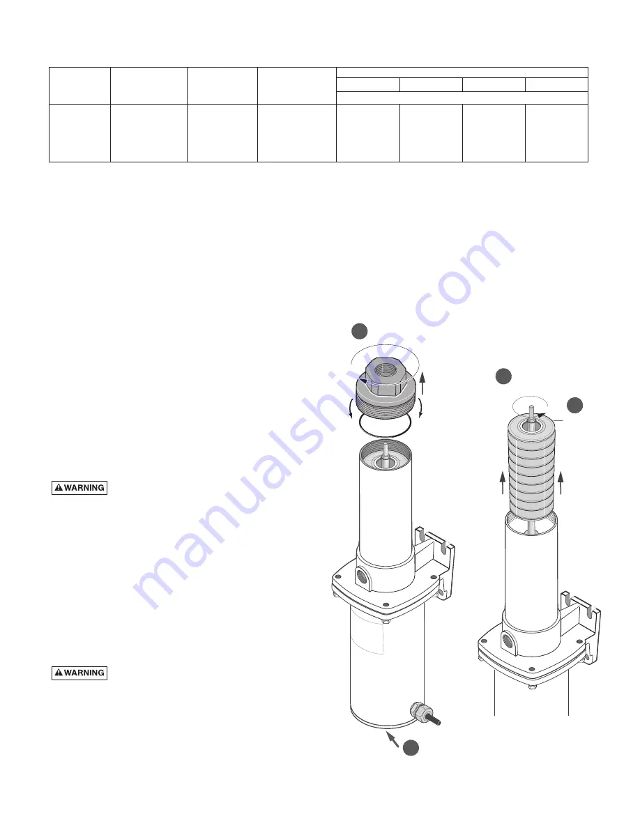
Impeller Stack Changeout
(See Figure 1)
Remove pump from service and mount vertically in vise (if
available) motor side down. Hold at center of motor. It may be
desirable to wrap motor with a shop rag to protect outside
surface.
Proceed as follows:
1. Attach pipe wrench to flats on discharge connection and
turn clockwise to remove (left hand threads).
2. Remove cap over shaft end. Hold shaft with a wrench on
the shaft flats.
Disconnect
from
po
w
er
so
u
rce.
Hold shaft flats.
2
Impeller
Stack
Snap
Ring
Remo
v
e
w
ith
Counter-clockwise
rotation.
3
4
1211 0
8
94 GS
1
Discharge
Connection
Remo
v
e
w
ith
clockwise
rotation.
Figure 1 – Impeller stack changeout.
TABLE I - RECOMMENDED FUSING AND WIRING
Wire Length
Motor
Volts/
S.F.
Branch Fuse
0’-50’
51-100’
101-200’
201-300’
H.P.
Phase
Amps
Rating Amps
AWG Wire Size
1
208-230/1
8.5-10.4
15
14
14
14
12
1
208-230/460/3
4.8/2.4
15/15
14/14
14/14
14/14
14/14
1-1/2
208-230/1
10.5-11.2
15
12
12
12
10
1-1/2
208-230/460/3
6.0/3.0
15/15
14/14
14/14
14/14
14/14


