Gilson Company, Inc.
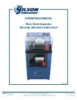
Micro-Deval Apparatus: MD-2000, MD-2000C & MD-2000F
Page 3
1.0 INTRODUCTION:
This manual is a guide to the operation and maintenance of
the Gilson MD-2000, MD-2000C or MD-2000F Micro-Deval
Apparatus. This unit has been designed and manufactured
to comply with current published specification requirements.
This manual makes no attempt to describe acceptable
test protocol. The operator is referred to the most
current revisions of ASTM, AASHTO or other governing
specifications for testing methods and procedures.
2.0 THEORY OF OPERATION:
The Micro-Deval Apparatus meets or exceeds the accuracy
and repeatability requirements of the “Standard Test Method
for Resistance of Coarse Aggregates to Degradation in
the Micro-Deval Apparatus” AASHTO Designation T 327,
ASTM D 6928, TexDot 845-49-40, and Ontario LS-618. As
well as the “Standard Test Method for Resistance of Fine
Aggregates to Degradation in the Micro-Deval Apparatus,
ASTM Designation D 7428 and Ontario LS-619.
3.0 PRINCIPLE OF OPERATION:
The MD-2000 Apparatus is supplied with two stainless steel
jars, stainless steel abrasive charges and a magnetic pickup.
A prepared aggregate specimen is placed in the abrasion
jar along with an abrasive charge of stainless steel balls
and water. The sealed jar is then placed on a set of rollers
and turned for a period of time. At test completion, the
aggregate sample is removed from the jar and tested to
determine degradation resulting from abrasion.
The MD-2000 controller functions as both a timer and a jar
revolution counter. Duration of the test may be controlled by either
method. Most current specifications call for the test to be based
on elapsed time at a specified speed. It has been demonstrated
that controlling the test by counting jar revolutions via an optical
encoder results in more consistent sample agitation.
In
TIME mode, operation terminates when the timer
counts down to zero from the time input by the operator.
In
REVS (Revolution Counter) mode, the user inputs
the desired number of revolutions into the counter.
Revolutions are then tracked via an optical encoder until
they reach zero, at which point the unit will stop.
4.0 UNPACKING & SET-UP:
NOTE: Save all packaging materials in case
instrument return is required.
The MD-2000 instrument is shipped in a sturdy box with
additional inside packing to reduce chances of shipping
damage. Inspect the outside of the box for external
damage. If no apparent external shipping damage,
remove internal packing and lift instrument from shipping
box.
Inspect the MD-2000 instrument for shipping damage.
Occasionally, damage may not be evident from outside
the shipping container. If damage is found, contact both
the freight carrier and Gilson immediately.
Locate instrument on smooth level floor surface.
Bottom of instrument has four adjustable feet to permit
leveling. Level the unit front to back and side-to-side,
using the top set of rollers as a reference. A short spirit
level may be placed across the rollers while leveling.
Check the bottom set of rollers in the same way. Some
“compromise” may be necessary to insure both sets of
rollers are as level as possible. When complete, tighten
the upper hex nuts on each foot against the frame to
lock the feet into position.
Location must allow the free flow of air through the louvers
located on both sides of the case. The MD-2000F model
features a cooling fan located in the rear panel to draw
additional air through the louvers. Allow adequate space
between the wall and the rear of the unit for proper
operation. DO NOT restrict airflow around the louvers
or fan.
WARNING!
MD-2000 requires a 115V/60Hz grounded power
supply for proper operation.
MD-2000C is equipped with a 115V/60Hz motor
with Thermal Protection. If the motor stops
operating, disconnect from the power supply, allow
it to cool down, and press the manual reset button
on the motor.
MD-2000F requires a 230V/50Hz grounded power
supply for proper operation.
The model number and electrical requirements are
clearly printed on the specification label, affixed
to the rear panel of the machine, adjacent to the
power inlet.
Any attempt to operate this device on a power
supply or connection it is not designed for will
damage the unit and void the warranty. If there
are any concerns, please contact Gilson prior to
connecting to the power supply.

