


- 18 -
System Appearance
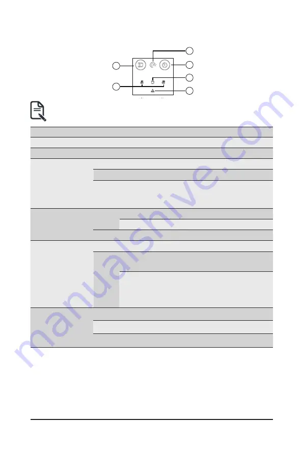
2-5 Front Panel LEDs and Buttons
1
2
5
3
4
6
• Systems equipped with RoT have different Status LED and ID LED indicators.
See
2-5-1 RoT LEDs
to check status.
No.
Name
Color
Status
Description
1.
ID Button
Press the button to activate system identification
2.
Reset button
--
--
Press this button to reset the system.
3.
Power button
with LED
Green
On
Indicates the system is powered on.
Green
Blink
System is in ACPI S1 state (sleep mode).
N/A
Off
• System is not powered on or in ACPI S5 state
(power off)
• System is in ACPI S4 state (hibernate mode)
4.
HDD Status
LED
Amber
On
Indicates locating the HDD.
Blink
Indicates accessing the HDD.
N/A
On
Indicates HDD error.
5.
System
Status LED
N/A
Solid On System is operating normally.
Red
Solid On
Critical condition, may indicate:
System fan failure; System temperature
Blink
Non-critical condition, may indicate:
Redundant power module failure
Temperature and voltage issue
Chassis intrusion
6.
LAN 1/2
Active/Link
LEDs
Green
Solid On Link between system and network or no access.
Green
Blink
Data trasmission or receiving is occuring
N/A
Off
No data transmission or receiving is occuring
Summary of Contents for S472-Z30
Page 1: ...S472 Z30 4U 50 Bay Single Processors Storage Server User Manual Rev 1 0...
Page 14: ...14 Hardware Installation 1 3 System Block Diagram...
Page 56: ...56 BIOS Setup 5 2 4 1 Serial Port 1 2 Configuration...
Page 64: ...64 BIOS Setup 5 2 8 PCI Subsystem Settings...
Page 75: ...75 BIOS Setup 5 2 17 Intel R i350 Ethernet Controller...


